

A heat sink that looks generous on a drawing can still fail thermally, and the reason is usually not the fin area. It is the interface: a base that does not sit flat against its component, a surface finish that leaves the thermal interface material uneven, or a mounting arrangement that bows the base away from the device. This guide covers what a machined heat sink has to achieve, how fin geometry and base flatness interact, how machining compares with skiving for fine fins, and how to specify the features that actually determine performance.
What must a machined heat sink achieve?
Move heat out of a small area into the air.
The function is to spread heat from a concentrated source across a base, transfer it into fins, and dissipate it by convection, so both the spreading and the fin area matter.
The thermal path has three parts. Heat leaves the component through an interface material, crosses into the heat sink base, spreads laterally through the base, and then passes into the fins where air carries it away. Each part of that path has a resistance, and the largest resistance is often not the fins but the interfaces: the contact between the component and the base, and the contact between the base and the fins if they are separate parts.
That is why the base’s flatness and the surface finish matter as much as the fin count. A base that is not flat leaves a thicker layer of interface material in the centre, which adds resistance exactly where the heat is concentrated. A finish that is too rough leaves voids; a finish that is too smooth can cause the interface material to pump out under thermal cycling.
The design consequence is that a machined heat sink is specified by two sets of requirements: the fin geometry that sets the surface area, and the base condition that sets the interface. Both are machining decisions, which is why the process is a good fit for parts where the thermal path is tight.
How does fin geometry affect performance?
It balances surface area against airflow.
Thinner, taller and more closely spaced fins add surface area, but they also restrict airflow, so beyond a point extra fins reduce performance rather than improving it.
The trade is between area and airflow. A fin dissipates heat through its surface, so more area is generally better, which argues for thin fins with a large height and close spacing. But close spacing increases the resistance to air passing between the fins, and in a natural-convection application the airflow is driven only by buoyancy, so a dense fin field can stagnate and perform worse than a more open one.
Fins also lose effectiveness along their height. A tall, thin fin is cool at its base and near the air temperature at its tip, so the upper portion contributes less than its area suggests. That is why very tall fins are more useful in forced-air applications, where the airflow is strong enough to keep the whole fin working, than in passive ones.
The practical guidance is to design for the airflow the application actually provides. Forced convection supports finer, denser fins; natural convection favours wider spacing and a shorter, thicker fin. Where thermal performance is critical, the geometry is usually confirmed with an analysis or a measurement rather than chosen from a table, and the machinability of the resulting fin field becomes the next constraint.
How does base flatness affect thermal contact?
It sets the thickness of the interface layer.
A flat base allows a thin, uniform layer of thermal interface material, which is the lowest-resistance condition the interface can achieve.
The interface between a component and a heat sink is never a perfect contact. Even two flat surfaces touch only at high points, with air filling the gaps, and air is a poor conductor. Thermal interface material fills those gaps, which is why its thickness matters: a thin, even layer conducts well, while a thick or uneven layer adds resistance.
Flatness is what controls that thickness. A base that is crowned will have its contact concentrated in the centre under a centrally mounted component, and the interface material will squeeze out there while remaining thick at the edges. A base that is concave does the opposite, leaving a thick layer under the component. Both cases increase resistance, and neither is visible on an inspection report that records only the overall height.
Surface finish completes the picture. A very rough surface leaves voids that the interface material cannot fill at the mounting pressure; a mirror finish can allow the material to migrate out of the interface over thermal cycles. The practical specification is a controlled flatness on the contact area and a finish that the interface material was designed for, both stated on the drawing rather than left to the machining default. The tolerance framework for those callouts is set out on 6CProto’s standards and tolerances page.
| Variable | Effect on thermal performance | Practical limit |
|---|---|---|
| Fin thickness | More area per unit volume when thinner | Machining forces and stiffness |
| Fin height | More area, less effective toward the tip | Airflow and fin stability |
| Fin spacing | More fins, less airflow between them | Convection mode |
| Base thickness | Better spreading from a concentrated source | Weight and material cost |
| Base flatness | Thinner, more uniform interface layer | Machining and fixturing capability |
| Base finish | Whether interface material fills the gaps evenly | Interface material specification |
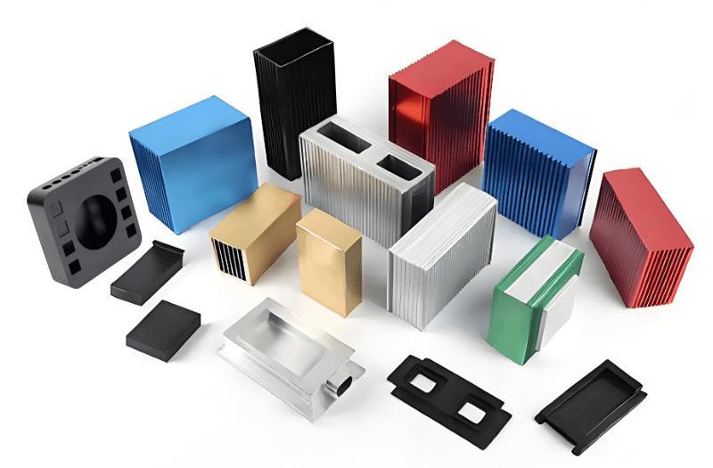
How does machining compare with skiving for fine fins?
Skiving produces finer fins; machining holds the base.
Skiving peels a continuous fin from the material, which allows very thin, tall fins, while machining cuts fins individually and is generally better for thicker pins and complex bases.
Skiving works by running a tool along the base material and lifting a fin from it, in the way a chisel raises a shaving. Because the fin is formed rather than cut free, it can be extremely thin relative to its height, and the base remains continuous with the fins, which removes an interface resistance. That is why skived heat sinks are used where space is tight and the fin field has to be dense.
Machining cuts each fin from the stock, so the achievable fin thickness depends on the stiffness of the tool and the forces involved. Thin, tall fins in a dense field are difficult because the tool has to pass between them, and the resulting surface finish on the fin flanks may require a finishing pass. What machining does well is the base: complex outlines, mounting features, pockets for components and threaded holes are all straightforward operations on a machined base.
Pin fins and complex geometries favour machining, because a mill can produce a pattern of pins that skiving cannot. Where a design needs both a dense fin field and complex base features, the answer is often a hybrid, with the fins produced by skiving and the base features machined afterwards or in a separate operation.
How does material choice affect the design?
Conductivity sets the spreading, density sets the weight.
Aluminium is the default for its balance of conductivity, weight and machinability, while copper is used where the thermal path is short and the heat flux is high.
Aluminium conducts heat well, weighs roughly a third of what copper does for the same volume and machines quickly, which is why it dominates heat sink design. Copper conducts better still, which helps where heat has to spread from a small source or where the fin field is limited by space, but its density and cost both work against it. The full trade-off is covered in the companion article on heat sink materials, and the grades available are listed on the aluminium and copper material pages.
Machinability differs between the two. Aluminium cuts quickly and holds a good finish; copper is gummy, tends to smear under the tool and requires more careful feeds and more frequent attention to chip evacuation. That difference shows up in the machining cost, which is part of the reason copper heat sinks are more expensive than the material price alone suggests.
Finishes then follow the material. Anodizing is common on aluminium for appearance and corrosion resistance, though the anodic layer has a lower conductivity than the metal and can affect the interface if it is allowed onto the contact face. Masking the base is therefore part of the specification. Where copper is used, a plating or a passivation step keeps the surface from oxidising, which would otherwise degrade the interface over time.
What should be inspected?
The base condition and the interfaces.
Inspection should confirm the flatness and finish of the contact area, the fin geometry, and the mounting features that position the sink against the device.
Base flatness is the measurement that matters most, and it should be taken on the contact area rather than across the whole part. Fin geometry is checked for thickness and spacing at representative points, since a pattern that varies across the field changes the airflow behaviour. And the mounting features, whether they are screw holes, a clip seat or a stud pattern, determine whether the sink can be held flat against the component, so their positions matter as much as their sizes.
For parts where the thermal path is critical, a functional check is more informative than dimensional inspection alone. That can be a thermal test with the actual interface material and mounting hardware, or a measurement of the interface layer after assembly. The result tells you what the part does rather than what its dimensions are.
6CProto provides quality inspection reports on request and follows each order with a dedicated project manager, so the inspection scope for a thermal part can be agreed with the drawing. The surface finish and preparation aspects are covered in the surface finish guides.
What drives cost?
Fin density, base complexity and material.
Machining a dense fin field consumes time in proportion to the number of fins and their height, and complex base features add setups.
The fin field is the largest cost element in a machined heat sink. Each fin is a cutting operation, and a fine, tall fin requires light passes and a tool that can reach the bottom of the channel without deflecting. That is why a small reduction in fin height or a modest increase in spacing can reduce cost significantly, and why the thermal analysis and the cost estimate should be done together rather than in sequence.
Base features then add their own cost. Pockets, bosses, threaded holes and cut-outs all require operations, and features on different faces require additional setups. Where the base is complex, the enclosure or mounting design often offers opportunities to simplify: fewer, deeper pockets and features consolidated onto accessible faces are cheaper than a pattern distributed across several faces.
Material and finish complete the price. Aluminium is the economical choice; copper adds material cost and machining difficulty. Anodizing or plating adds a process step and a masking requirement, since the contact face normally stays bare. Requests submitted through the quote flow receive a manufacturability review, so the fin field and the base features are assessed before the part is quoted. The quality practices behind thermal component inspection are published by NIST MEP.
Designing a heat sink that performs
Thermal performance comes from three things working together: enough fin area matched to the available airflow, a base thick enough to spread heat from a concentrated source, and an interface that is flat and smooth enough to keep the bond line thin. Machining contributes to all three, and it is the route that allows complex base features and precise contact faces on the same part.
The practical sequence is to define the thermal requirement, choose the fin geometry that suits the airflow, then specify the base flatness and finish that the interface material needs. Physical testing with the actual interface material and mounting hardware is what confirms the result, because the interface is where most heat sink performance is lost.
FAQ
What is the best material for a heat sink?
Aluminium is the practical default, because it combines good thermal conductivity with low weight, easy machining and reasonable cost. Copper conducts better and is chosen where the heat source is small, the flux is high or the available space limits the fin area, but its density and machining difficulty raise both weight and cost. Many designs use copper where the heat enters and aluminium where it dissipates.
What are the disadvantages of using a heat sink?
A heat sink adds volume, weight and cost, and it introduces an interface that has its own thermal resistance. It also needs airflow to work: fine, closely spaced fins perform well in forced convection and can stagnate in natural convection, where a more open fin field is often better. Where space is tight, the fin area available may be too small for the heat load regardless of the material.
How flat does a heat sink base need to be?
Flat enough that the thermal interface material forms a thin, uniform layer under the component. Crown or concavity concentrates the contact and leaves a thick bond line where the heat is greatest, which raises the interface resistance. The right value depends on the component footprint and the interface material, so the requirement belongs on the drawing as a callout on the contact area rather than as a general tolerance.
Should a heat sink be machined or skived?
Skiving produces thinner, taller fins than machining can, and it keeps the fins continuous with the base, which removes an interface resistance. Machining handles complex base features, pin patterns and mounting geometry better. Where a design needs both a dense fin field and a complex base, the two processes are often combined, with the fins skived and the base features machined afterwards. The standards, materials data and regulatory framework referenced in this article are published by ASTM committee B08, ASTM D3359, ASTM committee D20, ASTM committee E28.
If a thermal part has to meet a real heat load, send the model with the component footprint, the airflow available and the interface material you intend to use. 6CProto reviews heat sink designs for manufacturability and returns a DFM report with the quote, so fin geometry and base condition are settled before machining. Upload the file at the 6CProto quote page or send it to projects@6cproto.com.