

The question usually arrives with a part already designed: a bracket, a housing or a fluid component in metal, and an assumption that one of the two processes is obviously right. On simple geometry the answer is machining, because a machined face holds a tolerance that an as-built powder bed surface does not. On geometry with internal channels or consolidated assemblies, additive wins by default because there is no alternative route. The interesting decisions sit between those extremes, and they turn on cost at quantity, tolerance requirements and whether the design uses the freedom additive provides.
Is metal 3D printing cheaper than CNC machining?
It depends on quantity and on the geometry.
Machining is cheaper for simple shapes; additive wins when geometry is complex or volumes are too low for casting and forging.
Two cost structures are being compared. Machining charges machine time against a billet, and its cost per part falls as programming and fixturing are amortised over a batch. Additive charges build time against a powder bed, and its cost per part falls as parts share a build and as the geometry avoids supports and height. On a simple part at fifty units, machining usually wins on both counts. On a part with internal channels, machining may not be able to make it at all.
The comparison changes again when the design is allowed to change. A bracket consolidated from five machined parts into one printed component removes assembly operations, fasteners and inspection steps, and those savings do not appear in a per-part price comparison of the same geometry. That is the honest way to run the comparison: compare the assembly, not only the part.
Where the answer is genuinely close, the useful exercise is to quote both routes for the same quantity and list the operations included in each. Two numbers without scope are not a comparison.
How do tolerance and surface finish compare?
Machining wins on accuracy; additive wins on geometry.
A machined face reaches a defined finish and tolerance directly from the process, while a printed part arrives as a near-net shape that needs machining on any face where accuracy matters.
Machining removes material with a controlled tool, so the surface and dimensional result are predictable and repeatable across a batch. Powder bed fusion builds material up thermally, which leaves a rougher as-built surface and a distortion pattern that varies with geometry and orientation. Where a part needs a sealing face, a bearing bore or a press fit, the printed version is machined on those faces afterwards.
That leads to a hybrid route as the normal answer for metal parts with both requirements. The additive step produces geometry that cannot be machined, such as conformal cooling channels or curved internal passages, and the machining step produces the interfaces that must be exact. The two operations are complementary rather than competing, and the practical question is how much machining the printed part requires.
The framework for those callouts is set out on 6CProto’s standards and tolerances page. Confirming the achievable range for a specific feature before the design is frozen is faster than discovering the limit at first article.
How does cost per part change with quantity?
Machining amortises setup; additive amortises the build.
At one unit, both routes carry their full preparation cost; at higher quantities, machining spreads programming and fixturing while additive spreads build time across the parts that share a chamber.
The two curves behave differently because the fixed costs sit in different places. In machining, the setup, programming and fixturing are the fixed part, and the variable part is machine time per component. In additive, the fixed part is the build itself, and the variable part is how much of that build each part consumes, plus its post-processing.
That produces a practical pattern. For one to five components of simple geometry, machining is usually faster and cheaper because the part can be programmed and cut without a build cycle. For complex geometry, the printed route avoids tooling entirely and is competitive even at one unit. As quantity rises, machining continues to improve while additive improves only to the point where the bed is efficiently packed.
Above a certain volume, neither process is the answer: casting, forging or metal injection molding take over, with tooling amortised across a volume that additive and machining cannot match. Knowing where that crossover sits for a specific part is a useful part of the routing conversation.
| Factor | CNC machining | Metal 3D printing |
|---|---|---|
| As-produced tolerance | Reaches tight callouts directly | Near-net; interfaces need machining |
| Internal channels | Limited to drilled straight paths | Curved and conformal passages are routine |
| Simple geometry at low volume | Usually the faster, cheaper route | Requires a build cycle and post-processing |
| Consolidating an assembly | Multiple parts, fixtures and fasteners | One component replaces several |
| Material choice | Wide, including bar stock and castings | Limited to printable powder grades |
| Typical best use | Precision interfaces and simple shapes | Complex geometry and consolidated parts |
Which geometry can only be made additively?
Internal channels, lattices and consolidated assemblies.
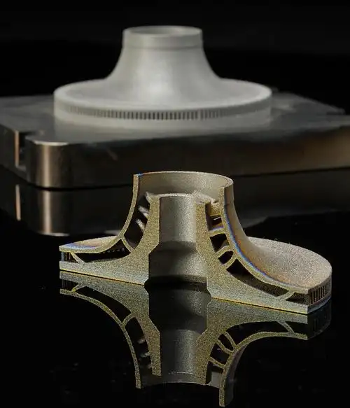
Conformal cooling passages, curved internal manifolds, graded lattices and multi-part assemblies merged into one component are the geometries that justify metal additive, because no cutting tool can reach them.
Conformal cooling is the clearest example and the one with the longest production history. A mold insert whose cooling channel follows the contour of the cavity cools more evenly than a straight drilled channel, which reduces cycle time and warpage. The channel is impossible to machine and straightforward to print, and the benefit is measurable in production rather than in the part itself.
Consolidation is the second. A hydraulic block assembled from a machined body and several fittings becomes a single printed component with internal routing, which removes joints, leak paths, assembly labour and the inspection steps that go with them. Lattices and topology-optimised structures form the third group, where material is placed only along load paths, and weight is removed from regions that a machined billet would carry as dead mass.
In all three cases, the design has to be created for the process. Adapting a machined design to printing usually produces a worse result than designing the part for the powder bed from the start, because the geometry that makes additive worthwhile is the geometry that machining cannot produce.
Which geometry should stay on a machining centre?
Simple parts and anything with a tight interface.
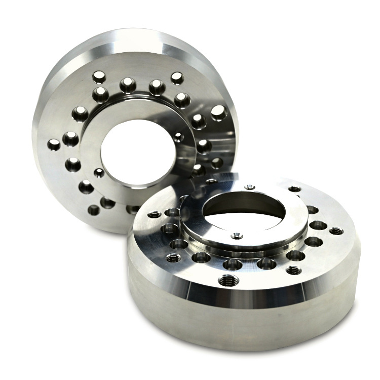
Blocks, shafts, flanges, bores and sealing faces are faster, cheaper and more accurate when cut from stock, and no additive advantage offsets the cost of printing and finishing them.
Machining is the right answer whenever the part’s value lies in its accuracy rather than its shape. A bearing housing, a spigot, a threaded fitting or a gasket land all depend on a controlled surface and a predictable dimension, which a cutting tool produces directly. Converting such a part to printing means adding a machining operation afterwards, so the comparison is between one process and two.
Machining also keeps a wider material range available. Bar stock and castings come in specifications and tempers that printed powder grades do not cover, and where a material’s certification is part of the requirement, that can settle the decision without reference to cost.
The pragmatic split is to keep precise interfaces on the machining centre and use additive only where it adds something the machining route cannot: a channel, a consolidation, or a weight reduction. Parts that fail that test are usually best left as machined components.
How do material behaviour and certification differ?
Same alloys, different process signatures.
A printed 316L part and a machined 316L part share a chemistry but not a microstructure, and where certification is required the process route becomes part of what has to be documented.
Additive manufacturing produces a material with a distinctive thermal history. Rapid solidification during the build leaves a fine microstructure with directional characteristics, and heat treatment is applied afterwards to relieve residual stress and, where required, to adjust properties. The result can be excellent, but it is not identical to wrought material of the same grade, and testing is normally specified against the printed condition rather than assumed from the wrought data sheet. The measurement methods used to characterise printed material are described in the NIST additive manufacturing program, and the process vocabulary follows the work of ASTM committee F42.
Machined components from bar stock inherit the certification of the stock, which is a well-established chain. For regulated applications, the printed route requires documented powder specification, build parameters, heat treatment and test results, which is the framework described for medical devices in the FDA guidance on technical considerations for additive manufactured medical devices. Where an application needs an independent assessment, certification bodies such as UL publish their additive service scope.
The materials available for either route are documented on the material pages, including titanium for both machined and printed parts, which is the quickest way to check whether a grade is available in the form the design needs.
How does lead time compare?
Machining suits simple parts; printing suits complex ones.
A machined component can be programmed and cut without a build cycle, while a printed part waits for a build slot and then for heat treatment and interface machining.
For a simple part, the machining route has fewer steps: prepare the model and program, set up stock, cut, inspect. The printed route adds a build, separation, heat treatment, support removal, interface machining and finishing, and each step has a queue of its own. That is why a printed bracket rarely beats a machined one on schedule unless the geometry forces the choice. The engineering context behind those steps is summarised on the ASME additive manufacturing topic page.
For complex geometry the comparison reverses. A part with internal channels cannot be machined at all in one piece, so the alternative route involves splitting it, machining each half and joining them, which adds design, welding or bonding, and inspection. Against that sequence, the printed route’s steps are simply the normal way of making the part.
The lead-time question is therefore better framed as which route has fewer uncertain steps. Both processes are predictable when they are the natural fit for the geometry, and both accumulate delay when they are being used to work around it.
When is the hybrid route the right answer?
When the part needs both freedom and accuracy.
Printing the blank and machining the interfaces gives internal geometry from the powder bed and tolerance from the cutting tool, and it is the standard route for parts that must do both.
The hybrid approach is not a compromise; it is how most production metal AM parts are actually made. The printed near-net shape provides the channel, lattice or consolidated structure, and the machining step brings the sealing faces, bores, threads and mounting features to their callouts. Heat treatment sits between the two, so that the part is dimensionally stable before it is cut.
Designing for the hybrid route means planning the allowance. Faces that will be machined need material left on them, and the fixture that holds the printed part during machining needs a surface to grip, which is often a printed pad or boss that is removed afterwards. Thinking about that at design stage is much cheaper than discovering at the machine that there is nothing to hold.
6CProto runs CNC machining and metal additive manufacturing in the same facility, which is what allows the printed and machined operations to be planned as one route instead of being split across two suppliers with different schedules and responsibilities.
Making the routing decision
The decision is rarely about which process is better in general. It is about which process makes this part, at this quantity, with the fewest risky steps. Simple geometry with tight interfaces belongs on a machining centre. Geometry with internal channels, consolidated assemblies or weight-driven optimisation belongs in the powder bed, with machining applied to the interfaces afterwards. Where both are needed, the hybrid route is the answer rather than a fallback.
Two questions resolve most cases. Does the design use a freedom that only additive provides? If not, machining is usually faster and cheaper. And do the interfaces need a tolerance that only machining can produce? If so, plan the operation before the design is frozen. The answer to those two questions is enough to choose the route, and it is faster to reach than a full cost study.
FAQ
What are the disadvantages of metal 3D printing?
Four limits matter commercially. As-built surfaces are rough and distorted, so accurate interfaces must be machined afterwards. The material range is narrower than the bar stock available for machining, and printed material has a different microstructure that may require separate testing. Build cycles and heat treatment add lead time. And support structures must be removed, which leaves marks on any surface they touched.
Is CNC machining harder than 3D printing?
They are difficult in different ways. Machining demands a setup, a fixturing strategy and toolpaths that avoid chatter and tool wear, and hard alloys such as titanium and nickel compounds make it more demanding still. Printing demands a build orientation, a support plan and post-processing that manages distortion. Which is harder in practice usually depends on the geometry, not on the process.
Can a printed metal part be machined afterwards?
Yes, and on most production parts it is. Machining after printing is how interfaces reach their callouts, and the printed geometry usually includes allowance for it. The part is typically heat treated first so that residual stress is relieved before cutting, and the machining fixture often grips a printed pad or boss that is removed at the end. Planning that allowance at design stage is what keeps the hybrid route efficient.
At what quantity does each process stop making sense?
Machining stays viable across a wide range, since the fixed cost of programming and fixturing is amortised by the batch. Additive improves only as long as parts pack the build chamber efficiently, after which the cost curve flattens. At higher volumes again, casting, forging or metal injection molding take over because tooling spread across thousands of parts beats both. The crossover is specific to the part, so the useful exercise is to quote two quantities and look at the slope.
If the routing decision is still open, send the model with the interfaces that must be exact and the quantity you expect. 6CProto runs CNC machining and metal additive manufacturing in the same facility, so the two routes can be quoted and compared from one manufacturing review. Upload the file at the 6CProto quote page or send it to projects@6cproto.com.