
Metal 3D Printing Services

Manufacture dense, high-strength metal components with SLM/DMLS laser powder bed fusion. Produce topology-optimized structures, internal channels, consolidated assemblies, and low-volume metal parts that are difficult to make conventionally.

  • Typical design tolerance: approximately ±0.2 mm
  • Layer thickness: 0.03 to 0.05 mm
  • Minimum wall thickness: 0.8 to 1.5 mm
  • Maximum build size: 427 × 460 × 527 mm

Start Your Metal Quote

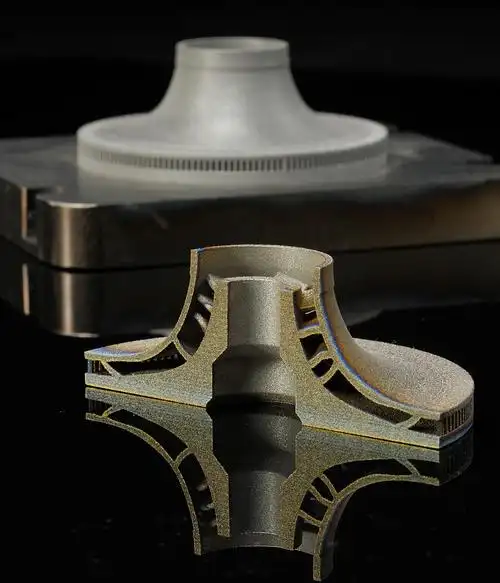
Metal 3D printed impeller with complex internal geometry and machined reference component

STEP  STP  SLDPRT  IPT  PRT  SAT  IGES  IGS  CATPART  X_T  OBJ  STL

All uploads are secure and confidential.

SLM and DMLS Metal Powder Bed Fusion

Metal 3D printing uses a high-energy laser to selectively melt or fuse metal powder layer by layer. The terms SLM, DMLS, and laser powder bed fusion are commonly used for closely related commercial processes. This page consolidates those intents into one primary service URL to prevent duplicate SLM and DMLS pages.

The process is intended for complex, high-value metal components where geometry, weight reduction, part consolidation, or internal flow paths justify additive manufacturing. For conventional prismatic metal parts and the tightest machined features, use our CNC machining services.
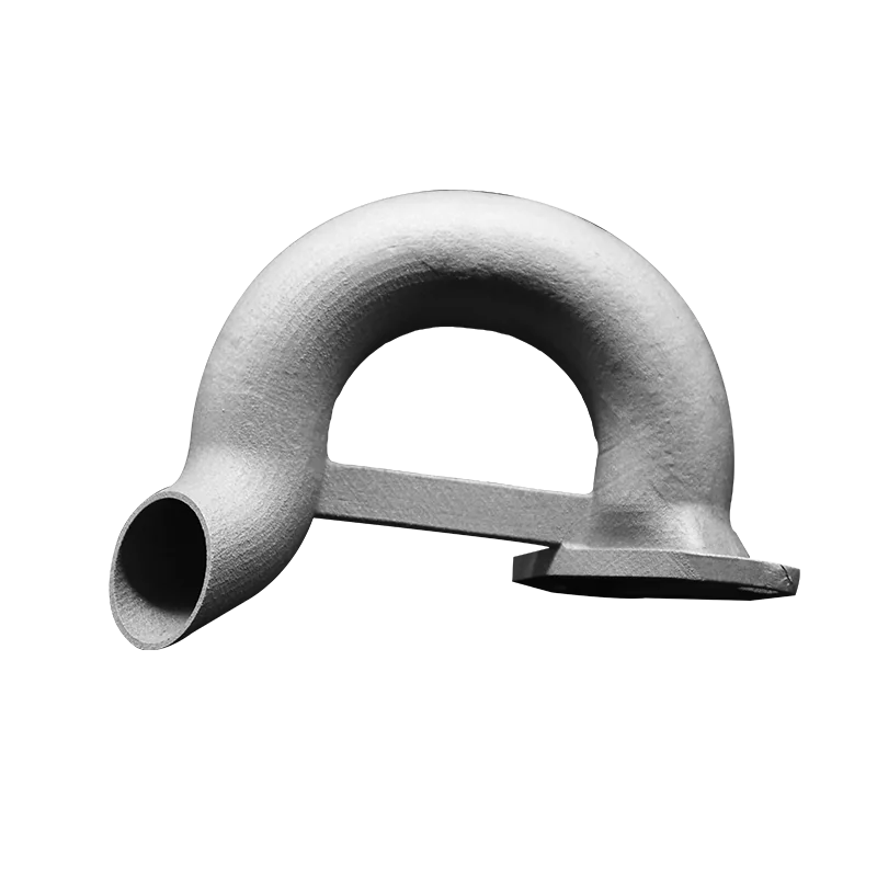
SLM metal 3D printed curved tube demonstrating support-managed complex geometry

From Metal Powder to an Inspected Component

Metal additive manufacturing is a production chain, not only a printing step. Thermal treatment, support removal, machining, and inspection should be planned from the start.

01 / ENGINEERING

DfAM and Build Review

We review alloy, orientation, supports, overhangs, distortion risk, machining stock, and inspection requirements.

02 / PRINTING

Laser Powder Bed Fusion

The laser consolidates selected powder regions while the build plate and supports control the part.

03 / THERMAL PROCESS

Stress Relief and Separation

Parts are heat treated as specified, removed from the plate, and separated from supports.

04 / COMPLETION

Machining and Inspection

Critical surfaces may be machined before dimensional, visual, and documented final inspection.

Metal 3D Printing Alloys

Select the alloy according to mechanical load, weight, temperature, corrosion, downstream machining, certification, and service environment.

Aluminum Alloys

Lightweight metal components with useful strength and thermal performance. Suitable projects may support machining, anodizing, polishing, and shot peening.

Stainless Steel 316L and 17-4 PH

Corrosion-resistant and high-strength options for functional components, manifolds, tooling, and industrial assemblies.

Titanium TC4 (Ti-6Al-4V)

High strength-to-weight ratio, corrosion resistance, and suitability for demanding aerospace, medical, and engineering applications.

Inconel

Nickel-alloy performance for high-temperature and corrosive environments such as energy, turbine, and extreme-service components.

Material control: Exact alloy designation, powder specification, heat treatment, certificates, and test requirements must be stated during quoting.

Metal 3D Printing Capabilities

Published printing values are starting points. Final requirements are set by alloy, part size, support strategy, thermal processing, machining, and inspection.

ParameterMetal AM CapabilityEngineering Consideration
ProcessSLM / DMLS / Laser Powder Bed FusionOne consolidated metal service intent
AlloysAluminum, 316L, 17-4 PH, Ti-6Al-4V, InconelExact grade and condition confirmed per project
Maximum Build Size427 × 460 × 527 mmUsable volume depends on alloy, supports, and geometry
Minimum Wall0.8 to 1.5 mmIncrease for loaded, broad, or heat-sensitive walls
Layer Thickness0.03 to 0.05 mmInfluences surface texture, detail, and build time
Design ToleranceApproximately ±0.2 mmCritical fits normally require machining allowance
Standard Lead TimeApproximately 6 business daysHeat treatment, machining, testing, and quantity may extend timing

Design for Metal Additive Manufacturing

Successful metal AM balances geometry freedom with support access, thermal stress, powder removal, machining, and inspection.

Build-Ready Design Practices

  • Use walls of approximately 0.8 to 1.5 mm or more.
  • Plan self-supporting angles and accessible support removal.
  • Add powder escape paths to channels and hollow regions.
  • Use fillets and gradual section transitions.
  • Add machining stock to critical bores, faces, and interfaces.
  • Define datums and inspection dimensions on a drawing.

Common Failure and Cost Risks

  • Large unsupported overhangs and horizontal ceilings.
  • Enclosed volumes that trap metal powder.
  • Broad thin plates prone to residual-stress distortion.
  • Sharp section changes and concentrated heat zones.
  • Finished-dimension CAD with no machining allowance.
  • Internal supports that cannot be removed.

When Metal 3D Printing Creates Real Value

Metal AM is justified by geometry and system value, not simply because a component is made of metal.

VALUE 01

Part Consolidation

Combine multiple manufactured pieces into one printed structure to reduce joints and assembly steps.

VALUE 02

Internal Flow Paths

Create curved channels, manifolds, and routing that conventional drilling cannot reach.

VALUE 03

Weight Reduction

Use topology optimization, lattices, and material placement around real load paths.

VALUE 04

Low-Volume Complexity

Produce complex metal components without dedicated casting dies or multi-part tooling.

Secondary Operations Complete the Metal Part

The printed near-net shape may require thermal, mechanical, and surface operations before it is ready for service.

Stress Relief and Heat Treatment

Thermal processing can reduce residual stress and develop the required alloy condition.

HIP

Hot isostatic pressing may be specified for selected critical applications and qualification plans.

CNC Machining

Critical bores, sealing faces, threads, and datums can be machined to achieve tighter requirements.

Support Removal

Parts are separated from the build plate and accessible supports are removed with geometry-specific methods.

Shot Peening and Polishing

Surface treatments can modify texture, appearance, and selected performance characteristics.

Alloy-Specific Finishes

Anodizing, passivation, and other finishes are selected according to substrate and project requirements.

Metal 3D Printing vs. CNC Machining

Choose the route based on geometry access, material form, inspection requirements, quantity, and total system value.

DecisionMetal 3D PrintingCNC Machining
GeometryInternal channels, lattices, topology optimization, consolidated partsAccessible surfaces, bores, pockets, and prismatic features
Material formQualified metal powder and layer-wise fusionWrought plate, bar, billet, or casting
Accuracy strategyPrint near-net, then machine critical featuresMachine critical geometry directly where tools can reach
Economic strengthHigh-complexity, lower-volume, system-level valueConventional geometry, broad material availability, tight features
Hybrid recommendation: Many successful programs use metal AM for the complex near-net shape and CNC machining for final interfaces.

Quality and Traceability for Metal AM

Quality planning should be proportional to alloy risk, end use, regulatory requirements, and the criticality of each feature.

Build and Alloy Review

Material, orientation, supports, thermal strategy, machining stock, and drawing requirements are reviewed before production.

In-Process Documentation

Required material certificates, heat-treatment records, and inspection plans should be agreed before quoting.

Final Verification

Visual and dimensional inspection is performed against approved requirements, with first-article inspection available when specified.

Regulated applications: Aerospace, medical, defense, and pressure-related programs require explicit review of certification, traceability, testing, and end-use obligations before acceptance.

What Customers Say About 6CProto

Metal 3D Printing FAQs

Metal 3D printing builds dense metal components layer by layer from powder using a high-energy laser. It is suited to complex functional geometries, internal channels, lightweight structures, and low-volume high-value parts.
They are closely related laser powder bed fusion terms. This page consolidates SLM, DMLS, and metal laser powder bed fusion intent into one primary service URL to avoid duplicate pages.
Published options include aluminum, stainless steel 316L, stainless steel 17-4 PH, titanium TC4 (Ti-6Al-4V), and Inconel. Exact grades and conditions require confirmation.
Typical printed design tolerance is approximately ±0.2 mm. Critical bores, faces, threads, and fits normally require machining allowance and secondary CNC machining.
The published maximum build size is 427 × 460 × 527 mm. Practical build volume depends on alloy, supports, orientation, thermal risk, and machine assignment.
Many parts require stress relief or alloy-specific heat treatment. HIP, solution treatment, aging, and other cycles depend on material, end use, and qualification requirements.
Yes. CNC machining is commonly used to finish datums, sealing surfaces, bores, threads, and other critical interfaces.
Published standard lead time is approximately six business days for printing. Heat treatment, support removal, machining, testing, inspection, and quantity can extend the total schedule.

Start a Metal Additive Manufacturing Project

Upload your 3D CAD file and 2D drawing with alloy, quantity, critical dimensions, heat treatment, certification, inspection, and finish requirements.