

A 3D printed part with a thread that strips on the third assembly is not a printing failure; it is a thread-strategy failure. Printed threads, tapped holes, and inserts each have a place, and the choice depends on the material, the load cycles, and whether the part will ever be disassembled. The designer who assumes a printed hole can be tapped like metal, or that a printed thread will hold like molded plastic, discovers the difference at assembly. The practical approach is to decide the thread strategy before the part is oriented, because the hole size, the layer direction, and the post-processing all depend on it.
What printed threads actually buy you and where they fail
Printing threads directly into the part is convenient: no secondary operation, no inserts, and the geometry is exactly where the CAD places it. The limits are strength and durability. Printed thread flanks are weaker than machined or molded flanks because the layer structure and surface roughness interrupt the thread form, and soft or brittle printed materials strip quickly under repeated assembly. A printed thread can work for a low-cycle, low-load joint in a strong material, but it is not a general answer for threaded fastening. The printed thread also carries the process’s tolerance, so the fit is less predictable than a machined or tapped thread.
Where printed threads fail is usually at the first thread and the root, where the load concentrates and the surface is roughest. If the joint is functional and will be assembled more than once, plan for a tapped or inserted thread rather than relying on the printed form.
Cutting threads into printed parts: tap size, hole strategy, and material limits
Tapping a printed hole works when the material is strong enough to hold the thread and the hole is sized for the process. The tap drill or the printed hole diameter must account for the material’s behavior: soft resins can deform or tear when tapped, hard filled materials can chip, and the layer structure can leave an interrupted surface that taps poorly. A common approach is to print the hole slightly undersized and tap it, which cuts clean threads in the material’s real structure rather than relying on the printed flank. The hole size, the tap, and the material should be tested together, because the printed hole dimension is not the same as a metal hole dimension.
Tapping direction and layer orientation matter: a tapped thread that runs across layer boundaries can peel layers at the thread root. Align the hole with the build direction where possible, or verify the thread strength on a sample before committing the design.
Inserts for printed parts: heat-set, ultrasonic, and press-in routes
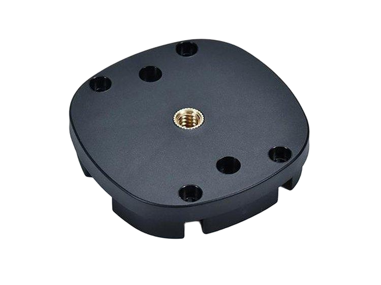
Threaded inserts are the reliable answer for printed parts that see repeated assembly. Heat-set inserts are common in thermoplastics: the insert is heated and pressed into a boss, melting the surrounding material to lock it in place. Ultrasonic insertion works similarly with a vibration press, and press-in or thread-forming inserts are used where the material and the boss design support them. Each route has a boss geometry: the hole diameter, the boss outer diameter, and the wall thickness around the insert must be sized so the insert does not crack the boss or pull out under load. The insert data sheet provides the recommended hole and boss dimensions, and the printed part’s tolerance should be tight enough to hold them.
Insert retention is a function of the boss design and the material. A thin boss with a heat-set insert can crack; a soft material may not grip the insert’s knurl; and a layer-oriented boss can split along the layer lines. Test the insert pull-out on the actual material and orientation, and add boss features — a thicker wall or a support rib — where the load demands it.
Choosing by load cycle, disassembly, and thread size
The thread strategy follows three questions: how much load, how many cycles, and will it be disassembled? A low-load, one-time assembly in a strong material can use a printed thread. A moderate joint with occasional service can use a tapped hole in a tough material. A joint that is cycled, torqued, or serviced repeatedly needs an insert. Thread size also matters: small threads concentrate load on a short engagement, while larger threads distribute it, and the engagement length should be sized for the material’s strength. The decision matrix is simple, and the answer usually lands on inserts for functional joints.
| Joint requirement | Printed thread | Tapped hole | Insert |
|---|---|---|---|
| One-time, low load | Workable in strong material | Workable | Overkill |
| Occasional assembly | Risky | Workable in tough material | Recommended |
| Repeated torque and service | Fails | Wears | Required |
| Small thread size | Weak | Short engagement | Best retention |
The table is the first filter; the material data and a pull-out test on the actual part decide the final call.
How to call out threaded features so the shop taps the right hole
Put the thread strategy on the drawing or the print note: whether the feature is printed as-threaded, printed undersized for tapping, or printed with a boss for an insert. State the hole size and the boss dimensions for inserts, the tap size where the part is tapped, and the thread class or the mating screw. Without the note, the shop prints the CAD hole as-is and the part arrives with a feature that was never designed for its fastener. The note also carries the testing requirement: if the thread is functional, name the pull-out or assembly test that verifies it, because a thread that has not been tested is a feature in name only.
The material and the post-process belong in the same note: a vapor-smoothed or coated thread changes size, and a thread tapped after finishing is different from one tapped before. The 3D printing team can review the boss and hole geometry against the insert or tap before the build, and the threading guide on this site covers the general thread callout standards that apply to the tapped and inserted routes.
Verifying the thread decision on the real part
Whatever the strategy, the verification is a test on the actual geometry. A printed thread that will hold a one-time assembly can be verified by assembling the mating screw and applying the torque; a tapped hole that will be serviced needs a cycle test that torques and releases the screw the number of times the product expects; an insert that carries the load needs a pull-out test at the rated force and temperature. The tests should use the production material, orientation, and post-processing, because each changes the result. A thread that passes on a flat test coupon can fail on the real boss where the layer direction and the wall thickness differ. The test record becomes the drawing’s proof: the thread feature is verified against the load and cycle requirement, not assumed from the material data sheet. If the test fails, the record shows which element failed — the printed flank, the tapped thread, or the insert — and the fix targets that element.
The same verification discipline applies when the printed part is a prototype for a molded or machined production part. The printed thread tells the team whether the geometry and the joint concept work, but the production process changes the thread behavior: molded threads carry different tolerances, and machined threads are stronger and more predictable. The transition plan should re-verify the thread on the production process rather than carrying the printed result forward. The drawing note should state the strategy and the test, so the shop, the quality team, and the future production process all reference the same requirement. That is how functional threads are designed in printed parts: the strategy is chosen by load and cycle, the geometry is sized for the insert or tap, and the result is verified on the part that will actually be used.
When inserts are not needed, the decision still deserves the same review. A low-load, one-time assembly in a strong printed material may use a tapped hole or even a printed thread, and the saving in parts and assembly time is real. The review should confirm the load, the material, and the assembly count, and the sample test should verify the thread holds. The common mistake is the reverse — using an insert everywhere because “inserts are stronger” — which adds cost and assembly steps to joints that never needed them. The thread strategy is a scale, not a rule: printed threads for the lightest joints, tapped holes for moderate service, inserts for repeated torque and load. The design review should place each joint on that scale with the load and cycle data, and the test should confirm the placement. A part with a mix of joint types is normal: a one-time screw for a cover and an insert for a serviceable latch can share the same housing, each chosen for its function.
If you are designing a printed part with functional threads, send the joint load, the cycle count, and the boss geometry to the 6CProto 3D printing team for a thread-strategy review before the part is oriented and built.