

A prototype assembly is rarely best made by a single process. The housing may print quickly in resin, the shaft needs the strength and precision of machined metal, and the threaded joints need inserts that neither process provides alone. Hybrid prototypes combine printed parts, machined metal, and standard hardware, and they succeed when each part is made by the process that suits its function and the assembly is designed for the joints between them. The design task is not choosing the one best process; it is dividing the assembly by function and engineering the interfaces where the printed and machined worlds meet.
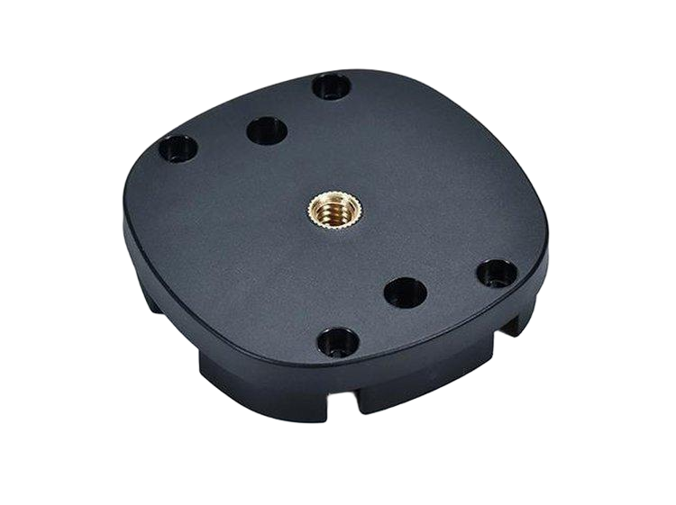
Dividing a prototype into printed and machined parts by function
The division follows function, not habit. Parts that are primarily geometry — housings, covers, brackets with complex shapes — are often better printed, because printing delivers the geometry without tooling. Parts that carry load, need precision, or bear threads are often better machined, because metal provides the strength and the tolerance. The same assembly can hold a printed cover, a machined shaft, and a machined insert for the thread, each chosen for its role. The division should also consider the prototype’s purpose: if the test is functional, the load-carrying parts need the production-like material and process; if the test is only geometric, printed parts may serve throughout.
The division is documented in the BOM with the process for each part, so the assembly team knows which parts are placeholders and which are functional.
Joining printed bodies to machined metal: fasteners, bonding, and press fits
The joints between printed and machined parts are where hybrid prototypes fail. Fasteners are the most serviceable route: a machined bracket bolted to a printed housing with a captured nut or an insert carries load and can be disassembled. Bonding joins printed plastic to metal with adhesive, spreading the load over the joint area but making the joint permanent. Press fits work for light, controlled joints where the printed material’s tolerance and creep are acceptable. The joint choice follows the load, the service plan, and the materials: fasteners for load and service, bonding for clean permanent joints, and press fits only where the printed part’s behavior is verified. The interface design — the boss, the insert, the clearance — is what makes the joint work.
The joint should be tested at the prototype stage, because the printed material’s creep and the bond’s strength are not assumptions to carry into production.
Threaded inserts and metal features that make printed parts repairable
Printed plastic threads strip, so the threaded joints in a hybrid prototype should use inserts or machined metal features. Heat-set or press-in inserts give the printed part a metal thread that survives assembly; a machined metal bracket can carry the thread that the printed housing cannot. The insert and the boss geometry should be designed together, with the boss wall sized for the insert and the load. The repairability is a prototype benefit: a printed housing with an insert that strips can be repaired by replacing the insert, and a machined part that fails can be replaced without reprinting the whole assembly. The design should keep the wear and the failure points replaceable.
The insert strategy follows the thread guide for printed parts, and the boss dimensions follow the insert manufacturer’s data.
Tolerance split: which surfaces must come from machining
The tolerance split is the engineering core of the hybrid. Printed parts carry printing tolerances and can move with temperature and moisture; machined parts carry machining tolerances and hold their geometry. The assembly should put the precise interfaces on the machined parts — the bearing seats, the alignment faces, and the datum surfaces — and let the printed parts carry the geometry that does not need precision. The drawing should mark which surfaces are machined to the tolerance and which are printed as-is, so the inspection verifies the right features and the assembly fits without rework. A hybrid that asks the printed part to hold a machined tolerance is a hybrid that fails its own premise.
The tolerance split also sets the assembly method: the machined parts locate each other, and the printed parts fill in around them, so the datum scheme should follow the machined structure.
Keeping the hybrid BOM simple enough to revise quickly
The hybrid’s advantage is speed, and the BOM should protect it. Use standard hardware where possible, keep the number of custom parts small, and make each part replaceable without redesigning the assembly. A hybrid with twenty custom parts has lost the speed that printing was meant to provide; one with a few printed parts, a couple of machined parts, and standard fasteners can be revised in days. The BOM should note which parts are expected to change, so the revision loop touches the printed parts and leaves the machined interfaces stable. The simplicity is what lets the prototype program learn fast and move to production without carrying the hybrid’s compromises forward.
The process-comparison article covers choosing one process; this page designs the assembly where several processes work together. When the function, the joints, and the tolerance split are designed together, the hybrid prototype is faster and more functional than any single-process version.
Verifying the hybrid and planning the production handoff
The hybrid prototype is verified at the assembly level: the joints are tested for the load and the cycles the assembly will see, the printed parts are checked for the creep and the tolerance behavior the design assumed, and the machined parts are verified for the fits and the alignment. The test results decide which parts are ready for production and which need the redesign. A printed cover that creeps under the fastener load needs a thicker boss or a different material; a machined bracket that does not align with the printed housing needs a datum change; and a bond joint that fails needs mechanical retention or a different adhesive. The verification turns the hybrid from an assembly of parts into an engineered system, and the record shows which elements are proven and which are still assumptions. The prototype that is verified as a system is the prototype that can move toward production with confidence.
The production handoff should plan the transition of each part. The printed parts may move to injection molding at volume, and the production design needs the draft, the wall, and the gate that the printed prototype did not; the machined parts may stay machined or move to casting; and the joints must be re-validated in the production materials. The hybrid BOM is the map for the transition, with each part’s production route and its validation gate named. The production handoff also decides which hybrid elements are permanent: some products stay hybrid in production — a molded body with machined inserts — and the production design should be developed for that route from the start. When the verification and the transition are planned together, the hybrid prototype is a genuine development vehicle rather than a one-off assembly.
The hybrid design should also plan the documentation, because the assembly’s quality history spans multiple processes and suppliers. The BOM records the process for each part, the joint specifications carry the fastener, the bond, or the fit details, and the inspection plan covers the printed and the machined features and the assembly-level fits. A hybrid that is documented per part and per joint can be traced, revised, and re-validated without re-deriving the whole design. The documentation is the map that lets the next engineer, the quality team, or the production supplier understand why each part is made as it is. When the hybrid is designed and documented as a system, its speed advantage is preserved — the revisions touch the printed parts, the machined interfaces stay stable, and the assembly keeps working.
The hybrid also needs a clear handoff for the parts that will change. The printed parts that are expected to iterate should be designed so the revision does not ripple into the machined interfaces: the mounting pattern and the datum features stay stable, and the printed geometry changes around them. The BOM note should mark the expected-change parts, so the revision loop is fast and the machined tooling is not re-cut for every printed change. That division is what keeps the hybrid’s speed advantage through the development cycle.
Finally, review the hybrid for the production risk it introduces. Each process in the hybrid adds a supplier, a tolerance, and a quality record, and the assembly inherits the variation of all of them. The design should minimize the number of critical interfaces and make each interface inspectable, so the production hybrid is controllable. If the hybrid is a development vehicle for a single-process production part, the handoff should consolidate the processes at the right volume; if the hybrid is the production design, the process control plan should cover every element. The hybrid is a tool, and the review should ask what it is a tool for.
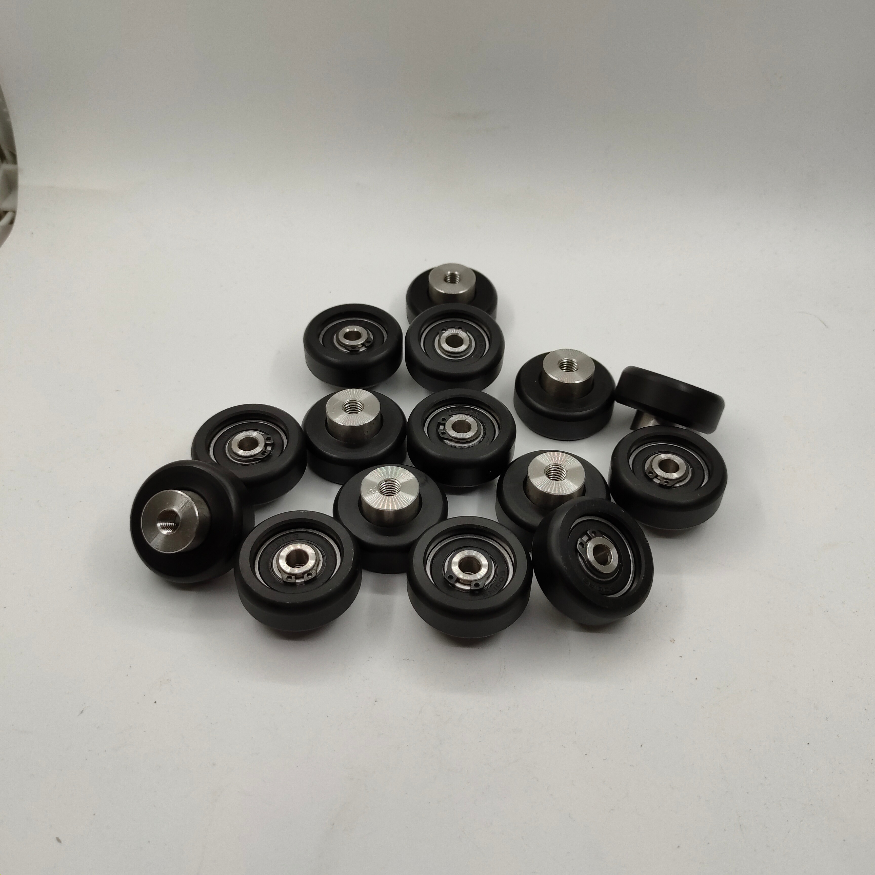
If you are designing a hybrid prototype and want the process split, the joints, and the tolerance plan reviewed, the 6CProto prototyping team can work from the assembly function to the printed and machined BOM.