

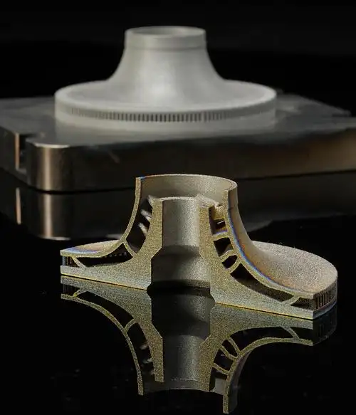
The first metal 3D printed part many teams make is a copy of a machined design, and it costs twice as much as machining while adding nothing. Metal printing earns its price only when the design uses the process: internal cooling channels that no tool can reach, lattice that saves weight where it carries no load, or consolidated assemblies that eliminate joints. Designing for DMLS or SLM means learning where the process wants supports, where powder must escape, and where the printed blank still needs machining — and those decisions are made in the CAD, not at the machine.
Why metal printing rewards a different design mindset
Machining starts from a solid block and removes material; metal printing builds the part layer by layer from powder, so the constraints are additive: every layer must be supported, every cavity must release powder, and every overhang must survive until it is supported. A geometry that is trivially machinable can be expensive or impossible to print, and a geometry that is impossible to machine can be routine to print. The design question is not “can this be printed?” but “what is this geometry worth that machining cannot deliver?”
Cost follows the same logic. Printing is charged by build volume, powder, and post-processing, so a solid block-shaped part is the worst possible use of the process. Design for printing by removing material where it is not needed, adding function where it pays, and planning the support and powder-removal paths at the same time.
Orienting the part: where supports, stress relief, and build height collide
Orientation sets the cost and quality of the print. Build height drives machine time, so a tall part is cheaper standing flat than standing up — but the standing orientation may need supports under overhangs and can leave layer-step surfaces where they matter. Overhanging surfaces that form an angle below roughly 45 degrees to the build platform (equivalently, beyond about 45 degrees from vertical, depending on how the reference angle is stated) typically need supports on many DMLS/SLM machines; state the reference angle and confirm the machine-specific limit, because the guidance is quoted from the platform or vertical in different sources. Supports mean extra material, slower builds, and marks to remove afterward. The orientation also interacts with stress relief: residual stress builds up during printing, and the part is stress-relieved before support removal, so the orientation affects the stress state that the part keeps.
Choose the orientation by function first: critical bores and sealing faces should avoid layer steps where possible, and the build direction should be aligned so the most stressed direction does not rely on interlayer bonds. Then minimize the cost within that constraint. The orientation that prints cheapest is rarely the orientation that performs best, and the drawing should say which surfaces are functional so the print orientation protects them.
Designing powder-escape routes and internal channels that clean out
Internal channels are metal printing’s signature feature — and its most common failure point. Powder that cannot escape stays in the part, shows up in the first test, and contaminates the system. Every internal cavity needs an opening large enough for powder to flow out, and the opening must be positioned so the powder actually drains. Small-diameter channels can be printed, but cleaning them requires flow, and the surface finish of as-printed channels is rough, so the design should state whether the channel is functional, cleaned, or inspected.
Blind internal volumes are the classic mistake. A cooling jacket that looks elegant in CAD but has no powder-removal path will ship full of powder or require a redesign. Design the drain holes from the start, plan to plug them if they are not functional, and confirm the cleaning method with the printer before the build.
Minimum walls, bosses, and holes: what is printable
Every printer has practical minimums, and they depend on the machine, material, and orientation. Thin walls can be printed but may distort or show porosity; small bosses may not survive support removal; small-diameter holes may close or need drilling after printing. The reliable approach is to design features above the printer’s stated minimums, add machining stock to features that need precision, and keep the geometry simple where function allows.
| Feature | Design guidance | Where machining follows |
|---|---|---|
| Thin wall | Above printer minimum; uniform where possible | Machined faces add stock for finish |
| Internal channel | Diameter above cleaning limit; powder-escape path | Ream or bore critical seats |
| Small hole | Oversize or drill after printing | Drilling gives true position and finish |
| Boss / thread | Add machining stock or print blank for tapping | Tapped or machined after stress relief |
Treat the table as a starting checklist; confirm the specific minimums with the printer for your material and machine, because generic numbers from one machine do not transfer to another.
The machining and finishing handoff
Metal printing rarely delivers a finished part. The printed blank is stress-relieved, supports are removed, and then critical surfaces are machined: sealing faces, bores, threads, and datums that the print process cannot hold. The design should plan this handoff by adding machining stock to functional surfaces, choosing datums that survive the print and support removal, and stating which features are print-as-built versus machined. The machining step is also where the part gains the inspection features it needs, because a printed surface cannot be measured the way a machined one can.
Plan the finish route with the material: some printed alloys are machined, bead-blasted, or coated, and the surface finish of the printed area affects fatigue and corrosion. The metal 3D printing service page lists the process and materials available; the design rules above are what make a part worth printing in the first place.
A decision example shows when printing earns its cost. A fluid manifold needs an internal cooling passage that follows a curved path no drill can reach, plus mounting bosses that must hold threads. Machining the manifold would require a split construction with welded or bolted halves; printing it as one part removes the joints, and the curved passage is exactly the geometry that justifies DMLS. The design review then works through the printed constraints: the passage needs a powder-escape opening and a cleaning plan, the bosses get machining stock for tapping after stress relief, and the sealing faces are machined after printing rather than accepted as-printed. The cost estimate covers powder, build time at the chosen orientation, stress relief, support removal, and the machining pass — and it still beats the split-and-weld route once assembly labor and leak risk are counted. The same part redesigned as a solid block would be a waste of the process, because it would carry none of the printed value and all of the printed cost. That contrast is the design rule in action: metal printing is justified by geometry that machining cannot produce, and the printed part is finished by machining where precision matters. When engineers evaluate a candidate part, the first question is not whether the printer can make it but whether the printed geometry removes cost or adds function that the machined alternative cannot — and only then do orientation, powder removal, and the machining handoff decide the details.
The design review gate for a printed part is a short list: confirm the geometry cannot be machined as economically; mark the functional surfaces for orientation; check every internal volume for a powder-escape path; size features above the printer’s minimums or plan machining; and price the full chain from build to final inspection. A part that passes the gate is a genuine additive candidate; one that fails it is usually better machined — and the gate is what stops the process from being used as an expensive way to make a machined shape.
Frequently asked questions
Can metal printed parts be welded to other components?
Yes, in many cases, but the printed material’s microstructure and any residual porosity must be considered. Confirm the alloy and the weld procedure with the printer and the welding engineer, and inspect the joint appropriately. Design the printed-to-welded interface with enough material and clean access, and validate the joint for the application rather than assuming printed material welds like wrought.
Why do printed parts need stress relief before support removal?
Printing builds residual stress as each layer cools, and cutting the part off the build plate or removing supports before stress relief can let the part distort. Stress relief relaxes that stress while the supports still hold the geometry, so the part keeps its shape. The sequence — stress relief, then support removal, then machining — is part of the process design, not an optional step.
How do you inspect internal channels in a printed part?
With the method matched to the channel: borescopes for access, flow or pressure tests for function, CT for internal verification when the risk justifies it. The drawing should state which channels are functional and how they will be verified, because an un-inspected internal channel is a requirement in name only.
Deciding whether printing is the right process
Metal printing is justified when the geometry adds function that machining cannot provide, and the cost is planned across the whole chain: powder, build, stress relief, support removal, machining, and inspection. If the design can be machined with equal function, machining is usually the better route; if the design exists only because printing makes it possible, then the orientation, powder-removal, and handoff decisions above are what make it successful. The 6CProto team can review the geometry against the printed and machined cost chain before you commit to the process.
If you are evaluating a metal printed part, send the geometry with the functional surfaces marked, and the machining and inspection plan will follow from the orientation you choose together.