

A prototype enclosure clicks together perfectly on the third printed revision — then the same snap fit cracks on the tenth part from the same file. Nothing changed in the CAD; the difference is that printed parts carry hidden directionality, and a snap beam is one of the few features where that directionality decides success. Snap fits in 3D printing fail for three reasons: the beam is oriented so the layers bend apart, the material cannot survive the deflection, or the clearance was copied from a machined-metal design without accounting for printing tolerance. Each failure is preventable at the design stage, and each has a distinct fix once you know how to read it.
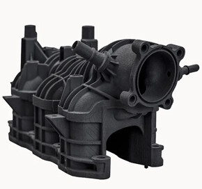
Printed snap fits differ from machined ones in three ways
Printed parts are strongest along their layer lines and weakest between them, so a snap beam must be oriented so bending does not pull layers apart at the root. In machined metal, snap-fit geometry is purely a spring calculation; in printing, the same beam can delaminate at half its calculated deflection if the layers run across the bend direction. The material also matters: nylon-based SLS and MJF parts flex repeatedly, while standard SLA resins are stiff and brittle and may crack on the first assembly.
Printing tolerance is the third difference. FDM, SLA, SLS, and MJF each hold different dimensional consistency, and small shifts in hole size, wall thickness, or feature scale change the engagement of a snap. Design clearances that assume machined tolerances will bind or rattle on a printer. The safe sequence is to design the snap slightly tight, print a test, and adjust toward the fit — printing makes that iteration cheap, which is the real advantage of prototyping a snap fit.
A printed snap beam needs length, a fillet, and moderate strain
A printed snap fit is still a cantilever: a long, thin beam with a hook, sized so the required deflection produces moderate strain. Lengthen the beam to reduce strain at a given deflection, keep the hook engagement just large enough to hold, and add a generous fillet at the root because sharp roots concentrate stress where the layer structure is weakest. Thickness should be chosen so the beam flexes rather than the hook bending or the wall tearing.
For a reusable snap, design the deflection to stay well below the material’s yield or creep limit over the intended cycle count; for a one-way snap, deeper hooks are acceptable because the part is assembled once. A common practical failure is a hook that is too tall: it looks secure in CAD but requires more deflection than the beam can survive. Model the assembly motion, not just the final position, and check the peak deflection the hook travels during insertion.
How does layer orientation change snap-fit strength?
What matters is the relationship between the beam axis, the layer normal, and the direction of the maximum tensile stress the bend creates. If bending pulls the beam’s tensile face across interlayer bonds, the root is weak; if the tensile stress runs along the layers, the beam behaves more like a continuous section. “Flat” and “upright” are shortcuts that depend on how the part is oriented and where the hook sits, so they should not be treated as universal rules — a beam that is flat in one part’s coordinate system can be upright in another. For each design, trace the deflection direction, check whether the maximum tensile stress crosses the layer boundaries at the root fillet, and prefer an orientation that keeps that stress within the layers.
The practical method is to identify the snap direction before orienting the part, then test the actual deflection direction on a sample. Once the build direction is chosen, check the root fillet location and the layer normal against the tensile-stress direction, and add margin where the stress crosses layers. Support removal adds its own surface and finish effects on the faces that carried supports. SLS and MJF remove the support constraint and are therefore popular for snap geometry, but they are not isotropic: layer-to-layer properties still differ, so orientation and root stress should be reviewed for powder-bed parts too, and validated on samples rather than assumed away.
Clearance must follow the printing process, not the CAD decimal
Design for the process tolerance, not the CAD decimal. Each printing process has a characteristic dimensional envelope, and features such as thin walls and small gaps can drift more than nominal sizes. Leave the snap slightly tight in the first revision, measure the actual force and deflection, and adjust in controlled steps. A snap that is a few tenths tight can be tuned by opening the hook or lengthening the beam; a snap that is loose cannot be fixed without a new part.
For one-way snaps, allow enough ramp angle that the hook deflects smoothly; for reusable snaps, add a lead-in chamfer on both parts and keep the release force within what the user can apply repeatedly. If the assembly includes other printed parts, remember that both halves carry tolerance, so the engagement stack includes two printed features, not one.
Reading the failure mode points to the right fix
The failure mode tells you which fix to apply. A crack at the beam root on first assembly points to orientation or brittle material. A snap that works at assembly but lets go after days points to creep in a soft material under sustained deflection. A clean break with little visible deformation points to a resin that is too stiff for the strain. A rattle points to clearance, and a snap that will not engage points to excess hook height or interference.
| Failure | Likely cause | First fix to try |
|---|---|---|
| Root crack on first assembly | Layers loaded across the bend or brittle resin | Rotate beam orientation; switch to impact-resistant nylon material |
| Lets go after days under load | Creep in soft or unfilled material | Reduce sustained deflection; stiffen beam; test at service temperature |
| Too stiff to assemble | Excess interference or hook height | Lengthen beam, reduce hook height, add lead-in chamfer |
| Rattles in assembly | Clearance too large for process tolerance | Tighten engagement; measure the printed dimension before changing CAD |
Test multiple samples rather than one, because printed parts vary within a build and between builds. If the snap is load-bearing or safety-relevant, do not rely on a single print: document the sample count, the material lot, and the test result, then decide whether the geometry or the process needs the change. The 3D printing service can run the material and orientation comparison for you, and the material pages on this site list the printed grades available for flexible or impact-resistant snap geometry.
Printed snap fits interact with post-processing more than machined ones. Sanding, tumbling, vapor smoothing, and clear coating all change the hook geometry and the surface friction, and a snap that was tuned on raw parts can bind, loosen, or crack after finishing. Plan the post-process sequence before tuning the snap: if the part will be vapor smoothed or coated, tune the geometry on finished samples, because the layer surface that carries the hook is exactly what those processes modify. Surface finish also changes the feel and the wear of a snap that is cycled repeatedly; a smooth, coated hook may slip more easily past the mating edge, while a rough as-printed surface can grab and wear. Document the finished state in the inspection note and keep a control sample of the tuned snap so later builds can be compared. When the printed snap is a proxy for a future injection-molded part, remember that molding tolerances, shrinkage, and material stiffness will shift the answer, so the printed test should validate the mechanism and the strain, not the final production dimensions.
Frequently asked questions
Can FDM parts be used for snap fits, or only resin and nylon parts?
FDM can work for low-cycle snaps if the beam is oriented with layers along the bending direction and the material is a tough filament, but the coarse layer structure limits detail and surface finish at the hook. For durable or cosmetic snaps, SLS or MJF nylon is usually the better choice; for fine, short-life snaps, SLA resins work if the strain is kept low. Match the process to the cycle count and the appearance requirement.
Should snap-fit dimensions be measured before or after post-processing?
Measure after the post-processing the part will actually receive, because sanding, tumbling, vapor smoothing, or coating changes hook size and surface friction. A snap tuned on raw parts can bind after a smoothing step adds or removes material at the hook. Record the process state on the inspection note so the design revision matches the finished part.
Can a printed snap fit be used for a production part?
Yes, when the production process is also additive and the material is qualified for the load and environment. The geometry rules transfer, but production tolerances, lot variation, and post-processing consistency must be revalidated on the production process. If the final part will be injection molded, the printed snap is a geometry test, not a material test — plastic grades and shrinkage change the answer at tooling.
Conclusion
Printed snap fits succeed when the design accounts for layer orientation, material strain limits, and process tolerance instead of copying machined-metal rules. Orient the beam with the load, keep the strain moderate, design slightly tight, and read the failure mode before changing the CAD. The print-test-adjust loop is the entire point of prototyping a snap: it is cheap, fast, and it converts assumptions into measured force and deflection.

If you are designing a snap-fit enclosure or clip and want a material-and-orientation recommendation before you print, send the beam geometry and cycle requirement to the 6CProto 3D printing team. The first printed sample will tell you more about the snap than a week of CAD review.