

The most common failure in a printed bracket is not a bad design: it is a good design printed in the wrong direction. Extrusion printing bonds each layer to the one below it, and that bond is weaker than the material inside a layer, so a load that pulls layers apart finds the weakest plane in the part. Orientation is chosen by the shop unless the drawing says otherwise, which means the load case is part of the specification. This guide covers why printed parts fail along layer lines, how infill and wall count affect stiffness, what annealing does to dimensions, and how to validate a load-bearing printed component.
Why do printed parts fail along layer lines?
Because the layer bond is the weakest plane.
Each layer is deposited onto a surface that has already cooled, so the joint between layers is a partial weld rather than a continuous material, and a tensile load across it can open the part.
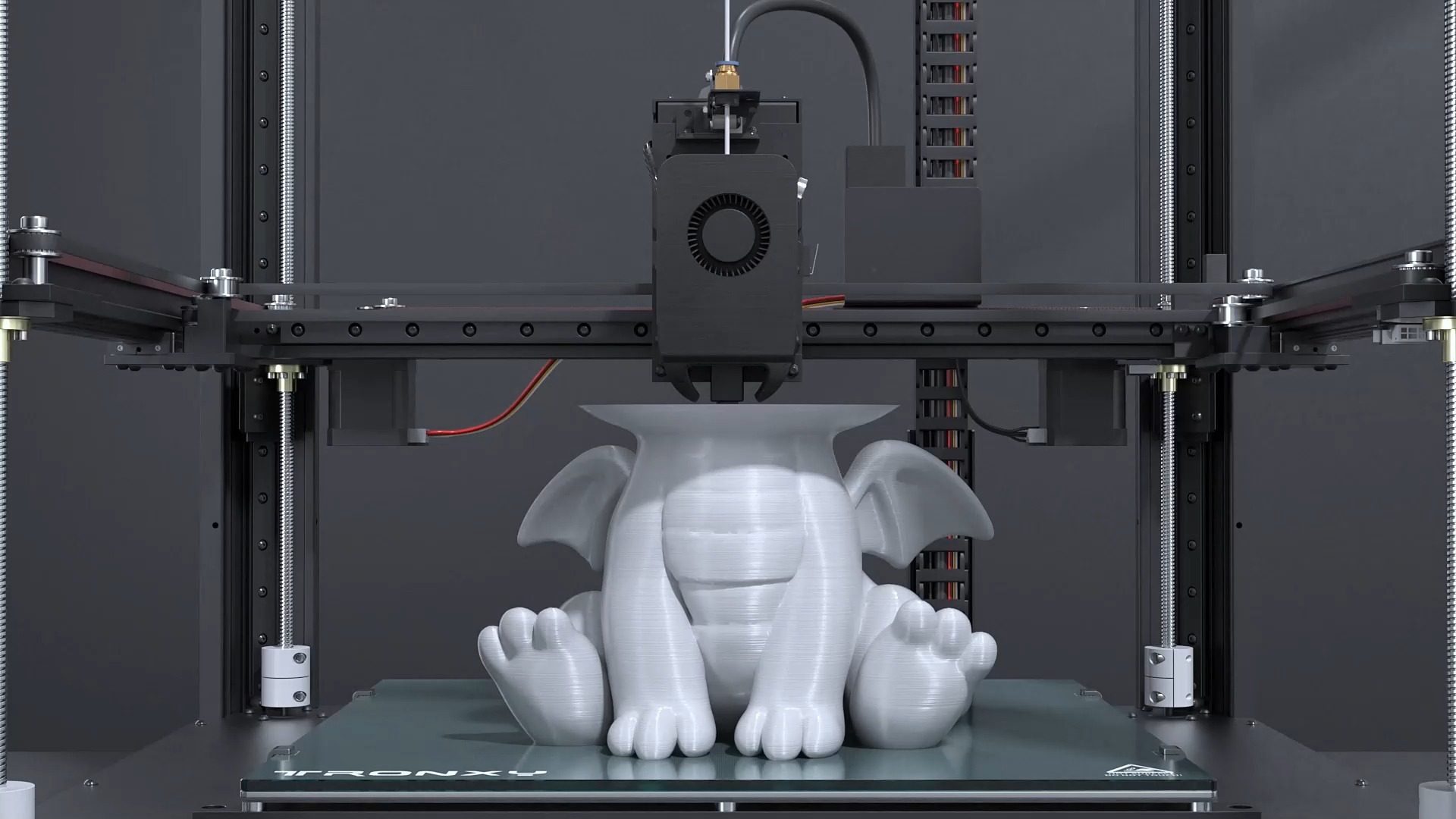
The mechanism is thermal. When a new layer is extruded onto the previous one, the two are at different temperatures, and the polymer chains at the interface only partially diffuse across the boundary. The result is a bond whose strength depends on the material, the extrusion temperature and the cooling rate. Within a layer, the extruded path is continuous material; between layers, it is a weld. The process terminology used here follows the additive manufacturing vocabulary maintained in ASTM F2792.
That is why a printed part can feel strong in the hand and fail suddenly in service. A load applied in the plane of the layers is carried by continuous material and behaves close to the bulk polymer. The same load applied across the layers is carried by the weld, and the failure appears as a clean separation along a layer line, which is unmistakable once seen.
The practical consequence is that orientation belongs in the design conversation, not in the machine queue. A part whose load case is unknown will be oriented for printability, which is a reasonable default but not a strength decision. The measurement methods used to characterise printed materials and their directional behaviour are described in the NIST additive manufacturing program.
How does anisotropy actually change design rules?
The part has two strength values, not one.
Design against the weaker direction: in-plane strength is close to the bulk material, while through-layer strength is lower, so features that carry load must be arranged to keep stress inside a layer.
Anisotropy means a printed component should be treated as directionally dependent material. In practice that changes three common design patterns. A boss that accepts a screw is loaded in tension when the screw is tightened, so it wants to be printed so that load runs in-plane rather than pulling a layer apart. A snap fit flexes repeatedly, so its hinge should be oriented so the flexing stress stays within a layer. And a cantilever bracket experiences its highest bending stress at the root, which should be arranged so the tension side of the bend is not a layer boundary.
Wall thickness and geometry interact with the same effect. A thick section printed as a solid mass has many layer boundaries stacked through its thickness, while a ribbed section carries load through material that is mostly in-plane. That is why ribs and gussets are often more effective in printed parts than increasing wall thickness, even when the section is stiffer in a molded equivalent.
Where a load genuinely has to cross layer boundaries, the options are a different material, a different process, or a mechanical solution such as a metal insert that carries the load through the joint.
How should orientation be chosen for a load case?
Put the highest stress in the plane of the layers.
Identify the load path first, then orient the part so that bending and tension run along the layer planes, even when that orientation costs more support material or print time.
The method is the same as for any structural part, with one additional constraint. Start by identifying how load enters and leaves the component: which face is bolted, which feature takes the force, and where the bending moment is highest. Then choose the orientation that keeps the tension side of that load inside a layer rather than across a boundary.
That decision often trades against other objectives. An orientation chosen for strength may require more support, take longer to print, or leave visible layer lines on a cosmetic face. Those trade-offs are worth making explicitly rather than accepting the default orientation, because a part that is cosmetically perfect and structurally weak is not a useful outcome.
For parts that will be ordered repeatedly, the orientation should be recorded with the part number. A second batch printed at a different angle is a different component in everything but name, and the difference will not appear until it is loaded.
How do infill patterns affect stiffness?
Pattern changes stiffness less than density does.
Increasing infill density raises stiffness predictably, while changing the pattern alters how the internal structure carries load and how the part behaves when it is compressed or bent.
Printed parts are rarely solid, and the internal structure is a design variable. A grid or rectangular infill creates a lattice that resists compression well in the direction of its walls. A triangular or honeycomb pattern distributes load more evenly and resists shear better. Concentric infill follows the part’s contour, which suits thin-walled components where the walls do most of the work.
| Lever | Effect on stiffness and strength | Cost implication |
|---|---|---|
| Orientation | Decides whether critical stress runs in-plane or across layers | Can increase support volume and print time |
| Wall count | Adds continuous material in the strong direction | Rises with material and print time; efficient per gram |
| Infill density | Raises stiffness where the section is compressed | Adds weight for less benefit at high fractions |
| Infill pattern | Changes how internal structure carries shear and compression | Neutral; no material change |
| Ribs and gussets | Increase stiffness with less material than a solid section | Small material cost; design time |
| Annealing | Improves layer bonding, relieves internal stress | Adds a thermal step and moves dimensions |
The more reliable lever, though, is density. Stiffness rises with the amount of material inside the part, and the relationship is roughly linear until the infill becomes dense enough that the external walls dominate. Below a certain density the internal structure contributes little, and the part behaves like a hollow shell.
For structural parts, the practical approach is to use walls for stiffness and infill for support. Several perimeters carry more load than a moderate infill percentage, because they are continuous material in the load direction rather than a lattice with internal boundaries. Where weight matters, removing material from the low-stress regions of the part is more effective than thinning the whole section.
Wall count or infill percentage: which matters more?
Wall count, for almost every load case.
Perimeters form a continuous shell around the part, so increasing wall count raises stiffness and impact resistance more efficiently than adding infill in the interior.
The reason is structural. The outer walls are the farthest material from the neutral axis in bending, so they contribute disproportionately to stiffness, and they form a continuous path in the plane of the layers, which is the stronger direction. Infill sits inside that shell and mostly resists compression, so its contribution is smaller until the wall count is already high.
That has a direct cost implication. Adding walls increases print time and material proportionally, but it does so where the mechanical benefit is greatest. Increasing infill from a low to a moderate percentage adds material in the region that contributes least, and it shows up as weight and time rather than strength.
The exception is a part loaded in compression through its thickness, where the internal structure is doing the work. For those parts, a moderate infill with a pattern that carries the compressive load, combined with an adequate wall count, is the right combination. As with orientation, the choice follows from the load case, which is why it belongs in the request rather than in a default profile.
What does annealing change, and what does it cost?
It improves layer bonding and moves the part.
Heating a printed part improves the bond between layers and relieves internal stress, at the cost of dimensional change, which has to be budgeted on any callout that matters.
Annealing takes the part above the point where the polymer chains can move, then cools it slowly. The result is better diffusion across layer boundaries, which raises through-layer strength, and reduced internal stress, which improves dimensional stability over time. For parts made from materials such as polycarbonate, nylon or PEI, it is a recognised step, and the grades available for printing are listed on the material pages.
The cost is dimensional. During annealing, the part relaxes, which can shrink it slightly and can change the shape of thin or unsupported sections. That movement is not uniform: it depends on geometry, on wall thickness and on how the part was oriented. Where a part has tight callouts, the allowance for annealing belongs in the design, and critical features are often machined after the thermal step rather than printed to final size.
Annealing also takes time, which extends lead time for parts that require it. For a fixture or a bracket where the load crosses layer boundaries, that is usually a worthwhile trade; for a visual part, it is usually not. Where a printed part is being qualified for industrial service, the engineering context for those decisions is summarised on the ASME additive manufacturing topic page.
How should ribs, bosses and joints be designed for strength?
Design them so load stays in-plane.
Ribs that run within a layer carry bending well, bosses need enough surrounding material to spread a screw load, and joints between printed parts should use laps and alignment features rather than butt joints.
Ribs are the most efficient way to add stiffness to a printed part, provided they run in the direction the load travels. A rib printed in the same plane as its parent wall acts as continuous material, while a rib standing across layers behaves like an additional layer boundary. Rib depth and spacing follow the same practice as molded design, with generous fillets at the root to spread stress.
Bosses that accept screws or inserts need care because the load is concentrated. The wall around a threaded boss should be thick enough to resist hoop stress, and the boss should be supported where it meets the parent wall rather than standing as an isolated column. Where the joint will be opened and closed repeatedly, a metal insert or a through-bolt with washers distributes the load more reliably than printed threads.
Where two printed parts join, the joint design matters more than in molded assemblies. A lap or tongue that overlaps in the load direction carries force through material rather than through an adhesive or a fastener alone, and alignment features keep the parts in position while fasteners are tightened. The design rules that support those choices, including wall thickness and fillet guidance, are collected in the 3D printing design tips library.
How do you validate a load-bearing printed part?
Test the geometry in the orientation you intend to use.
A validation test should reproduce the load direction, the clamping arrangement and the failure mode of the real application, because a test that loads a printed part in its strong direction proves very little.
The first requirement is fidelity to the real load case. If the part will be bolted at two points and loaded at a third, the test should reproduce that arrangement rather than supporting the part in a way that changes the stress path. Where the application applies load slowly, a sudden impact test measures something else entirely, and a part that passes it may still creep in service.
The second requirement is documentation of what was tested. Record the material, the orientation, the wall count and infill, and whether the part was annealed, because those variables define the specimen. Without that record, a pass does not transfer to the next order, and a failure cannot be diagnosed.
Where the test is destructive, keeping the failed specimen is worth the shelf space: the fracture path shows immediately whether the failure followed a layer boundary or ran through continuous material, which tells you whether orientation or section design is the problem to solve. Where a program requires independent verification rather than an internal test record, certification bodies such as UL publish their additive manufacturing service scope.
Designing for the load path
Anisotropy is not a defect to be minimised; it is a property to be designed around. The layer bond will always be the weakest plane in an extrusion-printed part, so the design task is to arrange the geometry so that the highest stress stays inside a layer. That means knowing the load case, stating it in the request, and recording the orientation that results so repeat orders match.
Two habits make the difference in practice. Identify the load path before choosing an orientation, and prefer ribs and wall thickness over infill changes when adding stiffness. Where neither approach is sufficient, the honest answer is that a printed thermoplastic may be the wrong material for that load, and a machined or molded component will serve the application more reliably. The standards vocabulary behind those design conversations is maintained in ASTM committee F42.
FAQ
What is the best print orientation for strength?
The one that keeps the highest stress inside the layer planes. In practice that means identifying where the part is clamped, where the load is applied and where the bending moment peaks, then orienting so the tension side of that load runs along the layers rather than across them. A part oriented for strength may need more support or show layer lines on a cosmetic face, and that trade is usually worth making.
Is vertical or horizontal orientation stronger?
Neither is universally stronger; it depends on how the load is applied. A part printed flat is usually stronger in bending across its length, while a part printed standing up is weaker against a load that pulls layers apart. The useful question is not which orientation is stronger in general, but which one places the critical stress in the stronger direction for this specific part.
Is 10% infill too weak?
It is too weak for structural parts, and often unnecessary for others. At low density the internal lattice contributes little, so the part behaves like a hollow shell and its stiffness comes almost entirely from the walls. For a load-bearing component, increasing wall count adds more stiffness per gram than raising infill. Where weight matters and the part carries little load, low infill with adequate walls is a reasonable combination.
Does annealing make a printed part substantially stronger?
It improves the bond between layers and reduces internal stress, which raises through-layer strength and makes behaviour more consistent over time. It is not a transformation, and it does not remove anisotropy. It also moves the part dimensionally, which has to be allowed for on any callout that matters. For parts loaded across layer boundaries, annealing is a worthwhile step; critical features are often machined afterwards.
If a printed part carries a real load, send the model with the load case and the faces that are clamped. 6CProto reviews extrusion printing projects for manufacturability, proposes an orientation that follows the load path, and returns a DFM report with the quote so the first build and the next one behave the same way. Upload the file at the 6CProto quote page or send it to projects@6cproto.com.