
When FDM Is the Practical Manufacturing Choice
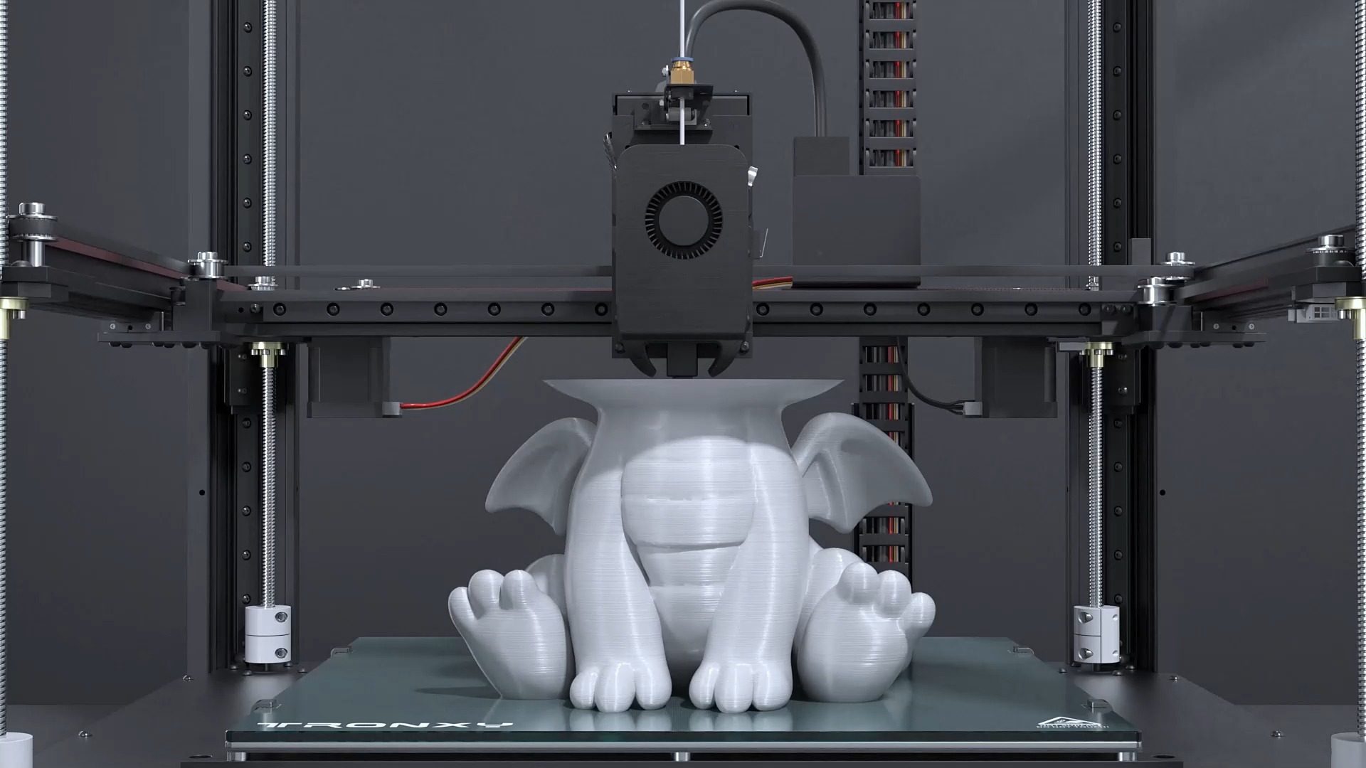
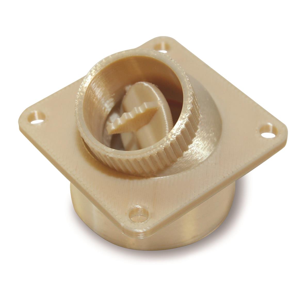
Fused Deposition Modeling (FDM) melts and extrudes thermoplastic filament through a nozzle, depositing material along programmed toolpaths to build a part layer by layer. It offers economical iteration, useful engineering materials, and the largest published polymer build envelope in our 3D printing range.
FDM is intended for cost-sensitive prototypes, large housings, jigs, fixtures, and functional checks. For smooth high-detail resin models, use SLA. For repeatable powder-bed nylon batches, use MJF or SLS.
Is FDM Right for Your Part?
FDM is not a universal substitute for every additive process. Use it when size, thermoplastic choice, iteration speed, and cost lead the decision.
Choose FDM When
- You need a cost-effective physical prototype.
- The part is large or can be assembled from sections.
- Material behavior matters more than a perfectly smooth surface.
- You need jigs, fixtures, guards, ducts, or ergonomic models.
- Fast design iteration is more important than tight cosmetic detail.
Consider Another Process When
- Small cosmetic details and smooth surfaces dominate: choose SLA.
- Repeatable nylon batch production is the goal: choose MJF.
- Support-free internal geometry is essential: choose SLS.
- The final part must be dense metal: choose Metal 3D Printing.
- Tighter machined fits are essential: consider CNC machining.
FDM Thermoplastic Material Options
Material choice changes stiffness, heat resistance, impact behavior, flexibility, print stability, and cost.
PLA
Cost-effective and easy to print for concept models, visual checks, educational models, and early design reviews.
ABS
A practical engineering thermoplastic for housings, fixtures, and functional prototypes requiring improved toughness.
PETG
Balances ease of printing, durability, and chemical resistance for functional prototypes and protective components.
Polycarbonate (PC)
Used for stronger, heat-resistant tooling, fixtures, and load-bearing prototypes when project requirements permit.
TPU
A flexible option for grips, protective parts, seals, cushioning features, and impact-resistant prototypes.
Material Review
Final grade, color, mechanical properties, and environmental suitability are confirmed during quoting.
FDM Size, Layer, and Tolerance Capabilities
Plan around the tradeoff between part size, layer height, surface quality, build time, and cost.
| Parameter | FDM Capability | Design Meaning |
|---|---|---|
| Process | Fused Deposition Modeling | Extruded thermoplastic filament |
| Materials | PLA, ABS, PETG, PC, TPU | Availability depends on grade, color, and project |
| Maximum Build Size | 1000 × 610 × 610 mm | Large-format capability; geometry review still required |
| Minimum Wall | 0.8 to 1.2 mm | Increase for tall, broad, loaded, or heat-sensitive walls |
| Layer Thickness | 0.05 to 0.4 mm | Fine layers improve detail; coarse layers reduce build time |
| Design Tolerance | ±0.2 to ±0.5 mm | Part size, material, orientation, and layer settings matter |
| Standard Lead Time | Approximately 5 days | Depends on size, build duration, quantity, and finishing |
FDM Part Strength Depends on Build Orientation
Unlike a molded part, an FDM component is direction-dependent. Load path and layer direction should be reviewed together.
XY Strength
Loads carried along deposited roads are generally more favorable than loads that pull layers apart.
Z-Direction Risk
Layer-to-layer interfaces can be the weaker direction, so orientation should follow the expected service load.
Support and Surface
Downward-facing surfaces may show support contact and should be positioned away from critical cosmetic areas.
What Drives FDM Printing Cost?
FDM pricing is strongly connected to machine time. Design changes can reduce cost without changing the external shape.
Part Volume
Larger envelopes and thicker sections increase machine time and material use.
Layer Height
Finer layers increase build duration but can improve detail and surface quality.
Supports
Overhangs require support material, removal labor, and possible surface cleanup.
Infill and Walls
Higher infill and more perimeter walls increase stiffness, weight, time, and cost.
FDM Design Guidelines
Design for extrusion paths, layer direction, support access, thermal shrinkage, and realistic assembly clearance.
Recommended Practices
- Use walls of approximately 0.8 to 1.2 mm or more.
- Orient primary loads within the layer plane when practical.
- Use chamfers or gradual overhangs to reduce supports.
- Add fillets around loaded corners and bosses.
- Provide clearance for printed assemblies and inserts.
- Specify critical faces and dimensions on a drawing.
Common Problems to Avoid
- Long thin towers and isolated pins.
- Large flat bases prone to warping.
- Critical cosmetic faces placed on support material.
- Threads printed without allowance or inserts.
- Loads that pull directly across layer interfaces.
- Unnecessary solid infill in large prototypes.
Common FDM Applications
FDM performs best when practical geometry, usable thermoplastics, size, and iteration speed lead the project.
Large Concept Models
Full-scale housings, ergonomic forms, architectural models, and presentation structures.
Jigs and Fixtures
Assembly nests, drill guides, inspection aids, guards, and lightweight shop tools.
Functional Prototypes
Ducts, brackets, enclosures, mounts, and mechanisms for fit and handling tests.
Flexible Components
TPU grips, bumpers, covers, cushioning features, and protective elements.
Educational Models
Durable demonstration parts and teaching models produced at practical cost.
Iteration Sets
Multiple design versions for rapid comparison before higher-cost production decisions.
FDM Finishing and Assembly Options
Post-processing can improve appearance, assembly durability, and the practicality of large multi-piece builds.
Support Removal
Temporary support structures are removed and contact areas are cleaned.
Sanding and Filling
Layer lines and support marks can be reduced for improved cosmetic appearance.
Painting
Prepared parts can be painted to specified colors or Pantone references.
Machining Critical Features
Selected holes or interfaces may be machined when geometry and stock allowance permit.
Threaded Inserts
Heat-set or mechanical inserts may improve repeated assembly performance.
Bonded Assemblies
Large models can be printed in sections, bonded, aligned, and cosmetically finished.
Quality Assurance for FDM Parts
Inspection requirements should match the prototype function, material, size, and downstream assembly needs.
Build Review
Material, orientation, supports, wall thickness, layer height, and critical surfaces are checked before printing.
Visual and Dimensional Checks
Finished parts are inspected against approved project requirements and drawings.
ISO 9001:2015 Controls
Documented quality management supports repeatable production and final shipment review.