

An aluminum part with a tapped thread strips on the third assembly, and the repair options start an argument: tap it oversize and use a bigger screw, install a helically coiled insert, or drill out the hole and press in a solid insert. Aluminum is soft, and its threads strip when the load, the cycles, or the assembly practice exceed what the tapped hole can carry. The insert-versus-tap decision is an engineering choice driven by the number of assembly cycles, the load, the repair situation, and the cost — and the answer is different for a new design than for a part already in the field.
Why aluminum threads strip and when inserts solve it
Aluminum threads strip because the material is soft and the thread engagement is small. A screw torqued into a tapped aluminum hole deforms the threads under load, and repeated assembly wears them; cross-threading accelerates the failure; and a thread that is too short for the load strips on the first torque. An insert solves the problem by providing a harder thread surface — steel or stainless — that carries the load without deforming the aluminum. The insert also spreads the load differently and can be replaced if it wears, which makes it the standard answer for joints that are assembled repeatedly or carry higher loads than the aluminum thread can support. The decision starts with the load and the cycle count: a one-time assembly with a light load may not need an insert, while a serviceable joint almost always does.
Inserting also changes the thread size: a helically coiled insert keeps the original screw size, while a solid insert may require a larger screw or a different thread. The design should preserve the mating hardware where possible, which is one reason the helical insert is common in repairs.
Helicoil vs solid inserts vs tapped threads
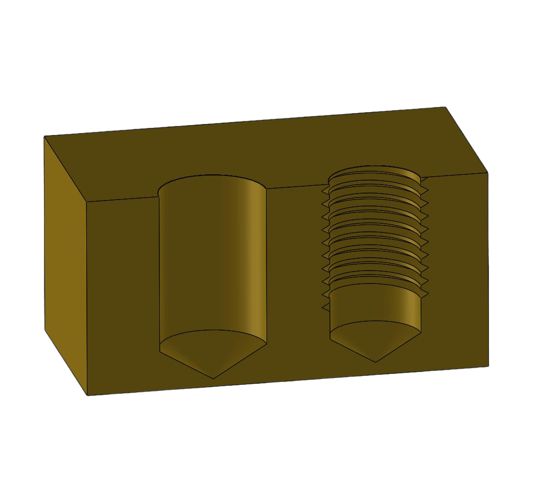
The three options have different profiles. A tapped thread is the cheapest and the lightest, and it works where the load is low and the assembly is infrequent. A helically coiled insert — the classic Heli-Coil — is installed into a tapped oversize hole and provides a steel thread that accepts the original screw; it is economical, works well in aluminum, and is the standard repair and design choice for many joints. A solid insert, such as a key-locking or threaded insert, provides a thicker wall of steel or stainless and carries higher loads, at a higher cost and with a larger installed diameter. The choice follows the load, the cycles, the space, and the repair history: tapped for the lightest joints, helical for the general serviceable joint, and solid where the load or the abuse justifies it.
The material of the insert also matters: stainless inserts resist corrosion, while a plain steel insert in a wet environment can corrode and seize. The insert material should match the environment and the mating screw.
Insert size and installation-hole rules
Every insert has a defined installation hole: the tap size for the insert, the counterbore depth, and the boss dimensions around it. The hole is tapped to the insert’s specified size, the insert is installed with the tool, and the surrounding material must be thick enough to hold the insert without cracking. The insert manufacturer’s data provides the hole and boss dimensions, and the design should follow them rather than guessing. In aluminum, the boss around the insert needs enough wall to resist the installation torque and the service load, and the drawing should carry the boss diameter and the hole depth so the shop machines the feature that the insert requires.
The installation process also matters: the insert should be installed straight and to the correct depth, and the tooling should be checked on a sample before production. A crooked or shallow insert fails the same way a tapped thread does.
Design guidance for new parts vs repair
The insert decision differs for new parts and repairs. In a new design, the engineer chooses the thread strategy up front: tapped for the light joints, inserts for the serviceable and loaded joints, with the boss geometry designed for the insert from the start. In a repair, the engineer works with the existing hole and the space around it: a stripped tapped thread can often accept a helical insert of the original size, while a badly damaged hole may need a solid insert or an oversized thread. The repair should restore the joint to its intended function, and the repair documentation should record the insert type and the resulting thread so the maintenance history is readable.
Repair inserts are also a design insurance: a joint that is expected to fail occasionally can be designed for an insert repair, with the boss sized for the insert even when the production part is tapped. The repair path is part of the design, not an afterthought discovered in the field.
Cost and lead-time comparison at prototype scale
At prototype scale, the cost difference between tapping and inserting is small per part but adds an operation and a part. Tapping is one operation on the machine; inserting adds the insert cost, the installation step, and the inspection. The comparison should include the failure cost: a tapped thread that strips in testing stops the prototype program and requires a repair, while an insert that fails can be replaced. For a prototype that will be assembled and disassembled repeatedly, the insert is usually worth the added cost; for a one-time fit check, tapping is sufficient. The lead-time difference is minor at small quantities, so the decision follows the test plan and the service plan rather than the price per part.
The threading and machining guides on this site cover the process; this page is the aluminum-specific insert-versus-tap decision. When the load, the cycles, and the repair plan are known, the thread strategy is a straightforward engineering choice.
Verifying the thread choice on samples
The thread strategy should be verified on samples before the design is locked. A sample joint with the production boss geometry is assembled and torqued to the service load, cycled the number of times the product expects, and tested for the failure mode the design must avoid. The tapped sample shows whether the aluminum thread holds; the insert sample shows whether the insert installation and the boss hold. The test results decide the strategy with evidence: if the tapped thread strips at the expected cycles, the insert is justified; if the tapped thread holds with margin, the insert is an unnecessary cost. The sample test also validates the installation process — the insert tooling, the hole, and the operator — because a production insert that is installed poorly fails the same way a tapped thread does. The verification record becomes the drawing’s proof, and it is the evidence the review needs when the strategy is questioned later.
The same verification applies across the part family. A housing with several threaded joints may mix strategies — tapped threads for the light covers, inserts for the serviceable fasteners — and each joint should be verified for its own load and cycle. The drawing should name the strategy per joint, so the shop installs the inserts where the design calls for them and taps where it does not. The mix is an engineering decision, not an inconsistency, and the sample verification is what proves each choice. When the strategies are verified and documented, the threaded joints are designed features with a test record, and the assembly behaves as the drawing promises.
The decision should also consider the thread’s position in the assembly and the service. A thread that is buried where the insert tool cannot reach, or a joint that will be serviced in the field where the insert replacement is difficult, may favor a different strategy than the load alone suggests. The service access, the assembly sequence, and the repair path belong in the review, because a strategy that is right for the load can be wrong for the service. The drawing should state the strategy and the reason, so the shop and the maintenance team understand why the joint is made as it is. When the load, the cycles, the access, and the service plan are all in the review, the thread strategy is a complete engineering decision rather than a default.
The drawing note should also state the assembly torque and the screw specification, because the thread strategy is part of the fastening system. A torque that exceeds the tapped thread’s capacity, or a screw with a different thread form than the callout, can strip a joint that was designed correctly. The torque and the screw belong with the thread callout, and the assembly instruction should carry them. When the thread, the screw, and the torque are specified together, the joint is controlled from the drawing to the assembly line.
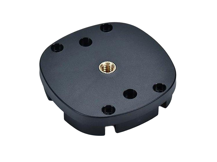
If you are deciding between tapped threads and inserts for an aluminum part, send the joint load, the assembly cycles, and the boss geometry to the 6CProto CNC team for a thread-strategy review before machining.