

A manifold that meets every dimensional requirement can still fail the moment it is put into service, and the reasons are almost always the same two: contamination released into the system, or a passage that does not hold pressure in the way the circuit requires. Both are verifiable before shipment, and both are difficult to detect afterwards without dismantling the assembly. This guide covers how manifolds are flushed and tested, what the acceptance criteria should state, and how the handling between machining and assembly determines whether the verification means anything.
Why does testing decide whether a manifold ships?
Because internal geometry cannot be seen once assembled.
A manifold’s passages are sealed inside the block once the valves and fittings are installed, so any defect has to be found before it leaves the shop.
The failure modes are specific. A passage drilled slightly too deep may connect two circuits that must remain separate, which produces an internal leak that no external inspection will reveal. A burr left at an intersection can break free under flow and travel into a pump or a valve. A sealing face with a scratch or a coating defect will weep at pressure. And contamination left in a passage from a later machining operation will be released into the system as soon as it is commissioned.
Each of those is detectable by a defined test, which is why testing is part of the production process rather than an optional extra. It is also why the test specification belongs on the drawing: without it, the shop applies whatever is standard, and the buyer discovers the difference when the block is in a machine.
How is pressure testing carried out?
With the passages isolated and monitored.
The block is pressurised, either passage by passage or with its cavities blanked, and any pressure loss or visible leakage is recorded against a defined acceptance criterion.
The general approach is to seal the ports of the circuit under test, apply pressure, and observe. Where the requirement is to confirm that two circuits are separate, the test pressurises one and monitors the other for any sign of pressure transfer. Where the requirement is to confirm the integrity of the block itself, the passages are pressurised together and the exterior is examined for weeping.
The parameters matter. Test pressure and hold time are specified by the application rather than chosen by the shop, because a test at the wrong pressure either fails to reveal a defect or exceeds what the block was designed for. Some specifications call for a test pressure above the working pressure, with the margin taken from the appropriate standard or from the customer’s requirement.
Cavity and port sealing during the test deserves attention. The plugs and blanking plates used to seal the ports have to hold the test pressure without leaking, so any leak detected has to be attributed correctly to the block or to the test setup. A shop that tests manifolds regularly has tooling for it, which is one reason a specialist supplier produces a more meaningful result than a general machine shop.
How is cleanliness verified?
By flushing the passages and measuring what comes out.
Fluid is passed through the manifold, collected, and analysed for particles, with the result compared against the cleanliness level the application requires.
The verification method usually involves flushing the internal volume with a defined fluid, collecting that fluid through a filter or a membrane, and then measuring the contamination it carried. Depending on the requirement, the result may be expressed as a particle count by size range, as a total mass of contamination, or as a comparison against a specified cleanliness code.
The requirement itself comes from the application. A manifold feeding a sensitive servo valve has a tighter specification than one feeding a simple cylinder, and the cleanliness level stated on the drawing should reflect that. Where the customer’s system already has a defined cleanliness code, quoting that code gives the shop something measurable to achieve.
Flushing is also a cleaning operation, not only a measurement. Passing fluid through the passages carries loose particles out, and a controlled flushing sequence is normally performed before the verification sample so that the measurement reflects what remains after cleaning rather than what was left by machining.
| Step | What it verifies | Method |
|---|---|---|
| Deburring | That intersections are free of loose material | Mechanical, abrasive flow, thermal or electrochemical |
| Flushing | That loose contamination has been carried out | Circulated fluid through the passages |
| Particle measurement | That the remaining contamination meets the level required | Analysis of the flush fluid |
| Pressure test | That the block and its circuits hold pressure | Pressurised with ports sealed and monitored |
| Cross-circuit check | That separate circuits remain separate | Pressurise one, monitor the other |
| Dimensional check | That ports and sealing faces meet the drawing | Gauging and measurement |
How do flushing and deburring relate?
One removes the burrs, the other carries them away.
Deburring removes material from the intersections, and flushing then carries the removed material and any other loose contamination out of the passages.
The relationship matters because flushing alone does not remove a burr that is still attached. A burr at a cross-drilled intersection is attached to the parent material until it is mechanically or chemically removed, and circulating fluid past it may dislodge it later in service rather than during cleaning. The deburring step has to be capable of reaching those intersections, which is why processes such as abrasive flow, thermal deburring or electrochemical deburring are used rather than manual work alone.
The sequence is therefore deburr, then flush, then verify. Deburring removes attached material, flushing carries the loose material out, and verification confirms that the level of remaining contamination is acceptable. Where the verification fails, the cause is usually that the deburring did not reach a location or that a later operation reintroduced contamination.
Contamination from later operations is the common oversight. Facing a sealing surface after the passages are clean produces chips that can enter the ports, and so does any subsequent machining, marking or assembly step. Cleaning after the last machining operation, capping the ports immediately and keeping them capped until final assembly are the practical controls.
What handling and packaging keep a clean manifold clean?
Caps, clean surfaces and no open ports.
A manifold that is verified clean and then stored openly will not stay clean, so packaging and handling are part of the cleanliness specification.
The requirements are straightforward. Every port is capped or plugged immediately after cleaning, and the caps stay in place until the manifold is assembled. Parts are stored in a clean area rather than in a general workshop, and they are handled with gloves where contamination or corrosion is a concern. Packaging protects the sealing faces and the port threads as well as the internals.
The duration matters too. A manifold that will be stored for months before assembly needs protection against corrosion as well as against particles, which may mean a preservative coating inside the passages. That requirement should be stated, because it changes the finishing steps and the packaging rather than being a handling preference.
Assembly conditions are the final consideration. A manifold assembled in a dusty environment will pick up contamination at the point where it is most difficult to remove, and the flushing that happened in the machine shop cannot be repeated once the valves are installed. Where the application is sensitive, the assembly environment is part of the specification, not merely a shop-floor habit.
What should the acceptance criteria state?
The test, the level and the documentation.
A manifold specification should name the pressure test parameters, the cleanliness level required, and the records that accompany the parts.
The pressure test parameters include the test pressure, the hold time and whether the test is applied to the whole block or passage by passage, along with the acceptance criterion. The cleanliness requirement should be expressed in the terms of the standard or code the customer’s system uses, so the result can be compared rather than debated. And the documentation should identify which of those tests were performed on the parts being delivered.
Where the manifold has features that cannot be verified dimensionally, such as the depth of an internal passage, the process record becomes the evidence. Recording the tool, the program and the depth control for each passage is more meaningful than a dimensional inspection that cannot reach the feature.
6CProto provides quality inspection reports on request and assigns a dedicated project manager to each order, so the test and cleanliness requirements can be agreed with the drawing rather than added after delivery. Process waste from machining and cleaning is handled under the framework published by the US Environmental Protection Agency, and the quality practices behind the documentation are described by NIST MEP.
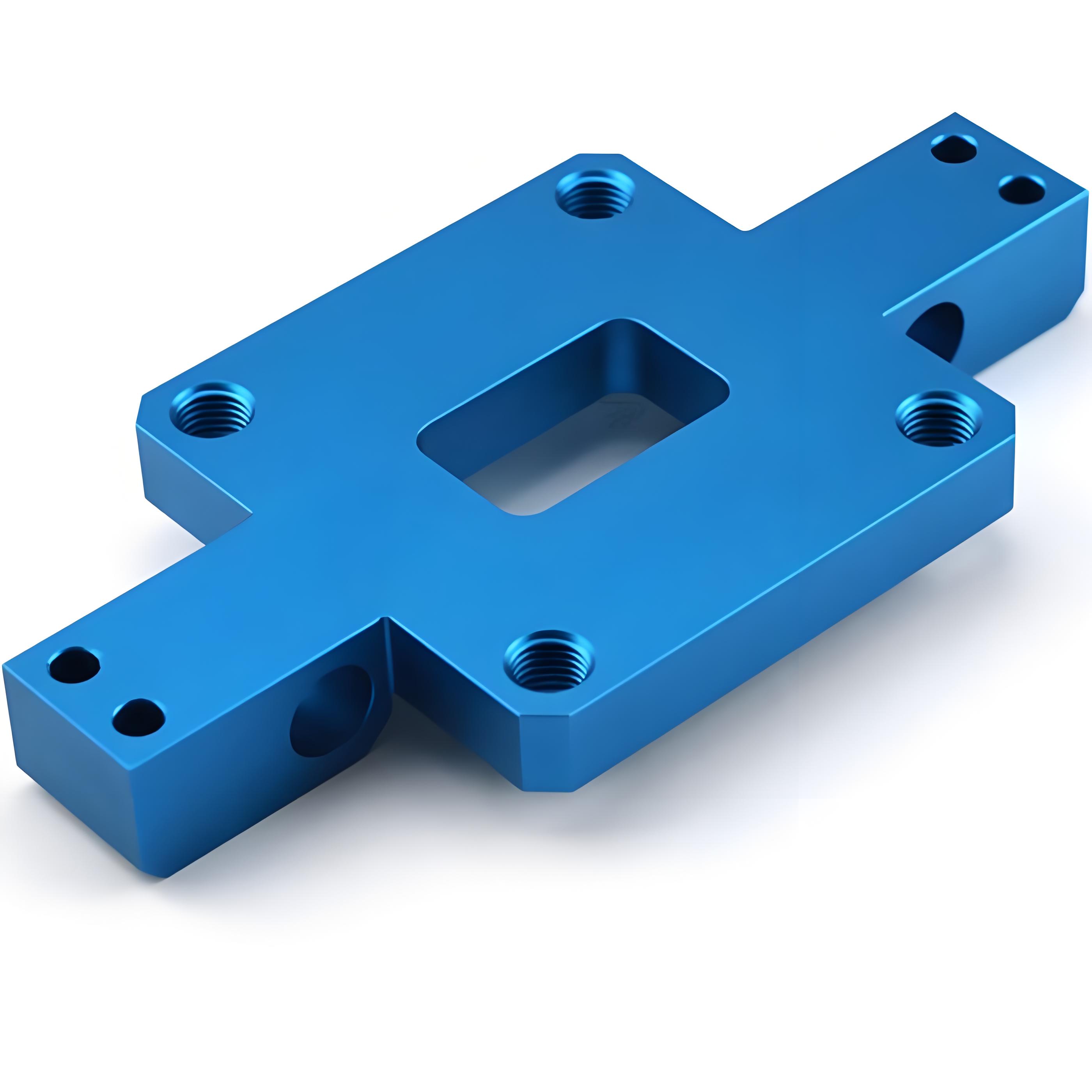
Verifying a manifold before it ships
Manifold verification covers three things: whether the block holds pressure, whether separate circuits remain separate, and whether the internal volume is clean enough for what it feeds. Deburring makes the first two possible to achieve reliably, flushing carries the debris out, and measurement confirms the result. Handling afterwards preserves it.
The practical habit is to put the test and cleanliness requirements on the drawing rather than in a conversation after delivery, because the shop needs them to plan the process and the buyer needs the results to accept the parts. Adding the packaging requirement, so the ports stay capped, closes the loop between verification and installation. The machining aspects of the same component are covered in the 6CProto article on manifold machining and passage layout, and the material grades are listed on the aluminium and steel material pages.
FAQ
How is a hydraulic manifold pressure tested?
The ports of the circuit under test are sealed with plugs or blanking plates, the block is pressurised to the specified test pressure, and the pressure is monitored for a defined period. Where the requirement is to confirm that two circuits remain separate, one is pressurised while the other is monitored for any transfer. The test pressure, hold time and acceptance criterion come from the application specification rather than being chosen by the shop.
What cleanliness level should a manifold have?
It depends on what the manifold feeds. A block supplying a sensitive servo valve needs a tighter level than one supplying a simple cylinder, and the appropriate requirement is usually the cleanliness code already used by the customer’s hydraulic system. Stating that code on the drawing gives the shop something measurable, and verification then compares the flush sample against it rather than against an impression.
Can flushing alone clean a manifold?
No, because a burr attached at a cross-drilled intersection will not be removed by fluid passing over it. Deburring has to reach those intersections, which is why methods such as abrasive flow, thermal deburring or electrochemical deburring are used for internal geometry. Flushing then carries the removed material and any other loose contamination out, and measurement confirms the result.
How should a manifold be handled after cleaning?
Every port should be capped or plugged immediately after cleaning and remain capped until the manifold is assembled. Parts should be stored in a clean area rather than a general workshop, handled with gloves where contamination or corrosion matters, and packed so the sealing faces and threads are protected. Where the parts will be stored for months, a preservative treatment inside the passages is worth specifying. The standards, materials data and regulatory framework referenced in this article are published by ASTM committee B08, ASTM D3359, ASTM committee D20.
If a manifold has to be verified before assembly, send the model with the test pressure, the cleanliness level your system requires and the packaging expectation. 6CProto reviews manifold designs for manufacturability and returns a DFM report with the quote, so deburring, flushing and testing are planned as part of the process. Upload the file at the 6CProto quote page or send it to projects@6cproto.com.