Michael Wang

Founder & Mechanical Engineer

As the founder of the company and a mechanical engineer, he has extensive experience in advanced manufacturing technologies, including CNC machining, 3D printing, urethane casting, rapid tooling, injection molding, metal casting, sheet metal, and extrusion.

Table Of Contents


Figure 1. Three-dimensional model of the 316 stainless steel water manifold.

Introduction

A water manifold is a connection and flow-distribution component used in cooling-water systems. It introduces, divides, and transfers coolant between pipes or other components. Its machining quality directly affects coolant flow, assembly accuracy, sealing performance, and product reliability. A poorly designed manufacturing process can reduce product quality and production efficiency while increasing tooling, equipment, and labor costs.

The component discussed in this article consists of a square main body, a hose-barb connection, an externally threaded connection, and intersecting internal flow passages. The machining process must ensure that the passages connect correctly and that the threads, sealing faces, and connection features meet the drawing requirements. The external surfaces, thread, and mating faces must remain free from dents, impact marks, and visible scratches that could interfere with assembly or sealing.

Leak tightness is equally important. After machining, the part must be deburred and cleaned, and its internal passages, threads, and connection faces must be inspected. A pressure-decay or equivalent leak test should confirm that the finished part has no leakage. The internal surfaces must also be free from burrs, rust, chips, weld residue, and other contaminants that could obstruct coolant flow or damage a seal. For this reason, internal visual inspection is an essential part of the quality-control plan.

This article presents a practical process design for machining the water manifold. It covers blank selection, operation sequence, fixturing, cutting-tool selection, internal-passage preparation, laser sealing, surface finishing, inspection, and handling controls.

1. Component Function and Structural Analysis

1.1 Component Function

The water manifold is made from 316 stainless steel and is designed to distribute cooling water. Its main features perform the following functions:

  • Square main body:Houses the internal flow passages and supports the hose barb and threaded connection. Its machined faces also provide location references for subsequent operations.
  • Hose barb:Connects to a flexible coolant hose. Its multiple annular ridges improve hose retention and help prevent the hose from pulling off.
  • Externally threaded connection:Connects the manifold to another component or pipe and provides installation and fastening capability.
  • Internal flow passages:Connect the hose-barb side to the threaded side so coolant can flow through the component.
  • Thread-end face and connection faces:Locate and seal against mating components. These faces must not have dents, impact damage, or other defects.

316 stainless steel provides good corrosion resistance and mechanical performance in cooling-water environments. However, it has a strong tendency to work-harden. Successful machining therefore depends on sharp tools, stable cutting conditions, suitable feeds and speeds, and effective cooling.

1.2 Main Structural Features

#### Square Main Body

The square body is the foundation of the part. It supports the connection features, contains the internal passage network, and provides the primary reference surfaces for milling, turning, drilling, and inspection. Its external geometry is mainly produced by CNC milling.

#### Hose-Barb Connection

The hose barb is positioned at an angle relative to the main body and includes several annular ridges. Because it is a rotational feature, its outside diameter, shoulders, grooves, and end face should be turned to maintain concentricity and surface quality.

#### External Thread

The threaded connection is located on the side of the square body. It includes a cylindrical outside diameter, an external thread, a relief groove, an internal bore, and a mating face. Turning is required to maintain concentricity among the bore, outside diameter, thread, and end face. The thread form and sealing face must be protected against damage throughout the remaining production process.

#### Intersecting Internal Passages

The bore through the hose-barb connection intersects the bore through the threaded connection inside the square body. These intersecting bores form the cooling-water passage. The two bores must meet accurately, and the intersection must be thoroughly deburred and cleaned to prevent loose material from obstructing flow or damaging downstream seals.

Because the hose barb and external thread point in different directions and are offset from the center of the square body, the component requires multiple setups and careful alignment. The process plan must control setup error and maintain a consistent datum system.

1.3 Manufacturability

The regular square body is straightforward to mill and provides stable datum surfaces for subsequent operations. The hose barb and threaded end, however, are offset rotational features and must be turned. Their different orientations require separate setups, increasing the risk of accumulated positioning error.

A standard CNC mill cannot efficiently create the required turned surfaces with the same concentricity and finish as a lathe. The two connection features should therefore be machined on a CNC lathe using dedicated eccentric fixtures, or on a suitable mill-turn machine. During machining and transfer, the hose barb, external thread, and connection faces must be protected from clamping marks, dents, burrs, and impact damage. Protective caps should be fitted immediately after the relevant feature passes inspection.

The internal passage cannot be completed conveniently from the two connection ends alone. A process access hole is therefore drilled from the side of the main body. After the intersecting passages have been machined, deburred, inspected, and cleaned, a plug is pressed into the access hole and laser welded in place to restore leak tightness.

Although the main body has a simple external shape, the offset turning operations, intersecting passages, welded access-hole closure, strict cosmetic requirements, and leak-tightness requirement make this a moderately complex part. Process control should focus on:

  • Concentricity of the two turned connection features
  • Repeatability of multiple setups
  • Complete removal of burrs and chips from intersecting passages
  • Integrity of the laser-welded plug
  • Protection of threads, sealing faces, and visible surfaces

Figure 2. Overall component dimensions: approximately 32 x 38 x 43.418 mm.

2. Recommended Manufacturing Route

The recommended route combines CNC milling, CNC turning with eccentric fixtures, deburring, ultrasonic cleaning, laser welding, polishing or mass finishing, visual inspection, and leak testing.

2.1 Blank Preparation

Use 316 stainless steel rectangular bar. The finished part is approximately 32 x 38 x 43.42 mm. A practical blank size is 35 x 40 x 45 mm, providing about 1 mm of machining allowance per side while taking standard material sizes into account.

When calculating the number of blanks obtainable from a 3,000 mm bar, include saw-blade kerf and cutting loss. A typical planning allowance is approximately 3 mm in addition to the required part length, but the final value should be based on the actual saw and production standard.

2.2 Milling the Square Body

Rough-mill all body faces on a CNC milling machine. A face mill can remove material efficiently from the top surface, while an end mill can rough the side faces. Finish-mill the body to achieve the required dimensions, flatness, parallelism, and perpendicularity, and to establish the datums used by subsequent turning and drilling operations.

Drill the side access hole and its locating counterbore according to the internal-passage layout. Leave approximately 0.5 mm of stock per side on the hose-barb and threaded regions for finish turning.

After milling, arrange the semi-finished parts carefully in transfer trays. Use cardboard, plastic separators, or dedicated cavities to prevent parts from contacting and damaging one another.

2.3 Turning the Externally Threaded Region

Mount the milled body in an eccentric fixture on a CNC lathe. Locate the part from the established body datums and align the threaded-connection axis with the spindle axis.

Machine the threaded region in the following sequence:

  1. Face the end.
  2. Turn the outside diameter.
  3. Drill or bore the center hole and internal passage.
  4. Machine the thread-relief groove.
  5. Cut the external thread.
  6. Chamfer the required edges.

Maintain concentricity among the outside diameter, bore, thread, and connection face. Inspect the finished thread with a GO/NO-GO thread ring gauge. After acceptance, remove chips and coolant with clean compressed air, dry the surface, and install a protective cap.

2.4 Turning the Hose-Barb Region

Use a second eccentric fixture, or a suitably adjustable dedicated fixture, to align the hose-barb axis with the lathe spindle. Locate the component from the machined body datums.

Machine the hose-barb region in the following sequence:

  1. Face the end.
  2. Drill or bore the internal passage.
  3. Rough-turn the outside diameter.
  4. Turn the stepped diameters and annular ridges.
  5. Chamfer the edges.
  6. Finish-turn the functional surfaces.

Maintain concentricity among the barb outside diameter, ridges, shoulders, and bore. Because the hose barb is relatively slender, control cutting forces to prevent vibration, tool deflection, or part deformation. After inspection, fit a protective cap and place the part in a dedicated tray.

2.5 Deburring the Internal Passages

Remove burrs from all bore entrances, the process access hole, and the internal bore intersection. Use a purpose-designed deburring tool, scraper, flexible abrasive tool, or another validated method suitable for the passage geometry.

Blow through all openings repeatedly with clean compressed air. Areas that cannot be viewed directly should be checked with an industrial borescope to confirm that no visible burrs or loose chips remain.

2.6 First Ultrasonic Cleaning

Use ultrasonic cleaning to remove machining oil, fine chips, and loose contaminants. Follow with clean, high-pressure air to dry the internal passages and remove residual water.

The access hole should not be sealed until the internal passage has passed both cleanliness and visual inspections.

2.7 Plug Installation and Laser Welding

Press a correctly sized plug into the access-hole counterbore using a hand press or controlled pressing fixture. The plug must seat in the correct position without tilting or becoming loose.

Laser weld the plug around its perimeter. Control laser power, travel speed, focal position, and heat input to produce a continuous weld without excessive distortion, undercut, porosity, cracking, or burn marks. Inspect the weld visually and perform an initial leak check before continuing.

2.8 Weld Finishing

Polish the welded area until it meets the drawing’s dimensional and appearance requirements. Avoid removing excessive material or creating a depression around the weld.

2.9 Overall Surface Finishing

The main body must not show obvious milling marks, scratches, dents, or impact damage. For small batches, manual polishing is practical. For higher volumes, vibratory finishing or another validated mass-finishing process can improve consistency and reduce manual labor.

Protective caps must remain on the hose barb and external thread during polishing or mass finishing. The process must not damage the thread form, round over functional edges, collapse sharp corners, or cause dimensional nonconformance.

2.10 Final Cleaning

Remove the protective caps and place the parts in a dedicated cleaning basket. Ultrasonically clean the external surfaces and internal passages to remove polishing compound, finishing media, oil, and other residues. Dry each passage with clean compressed air.

2.11 Leak Testing

Install the part in a dedicated test fixture and seal the hose-barb and threaded connections. Introduce air at the pressure specified by the product drawing or customer standard and hold it for the required time.

Inspect the internal passage, connection interfaces, and especially the laser-welded access-hole plug. The permitted pressure drop or leakage rate must follow the approved product specification. Any part that exceeds the limit must not proceed to final packaging.

2.12 Final Inspection and Packaging

Perform 100% inspection of critical dimensions and cosmetic surfaces. Use a borescope or automated vision system to inspect the internal flow passage, including the bore intersection and welded area, for burrs, weld spatter, rust, chips, or other residue.

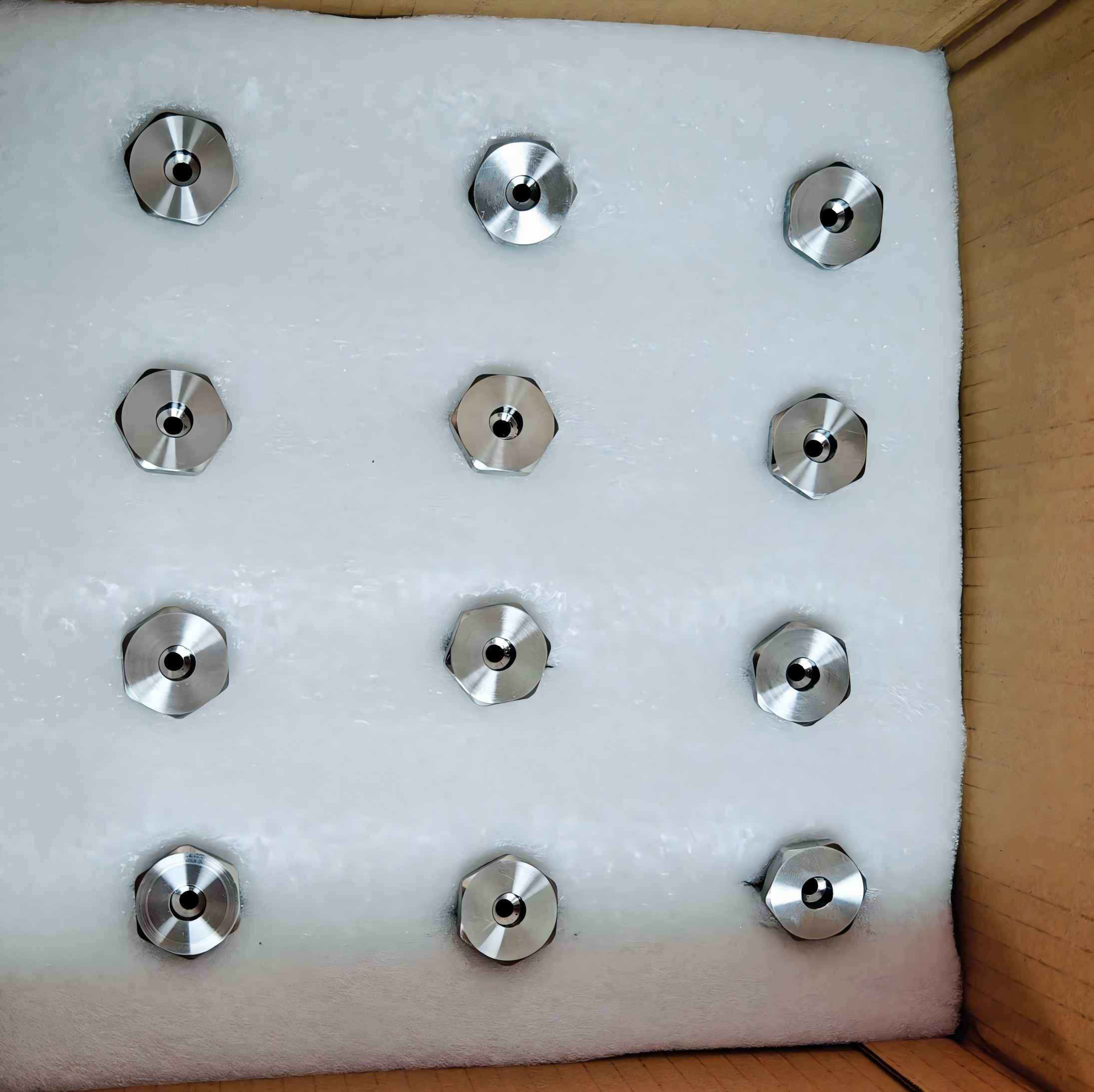
Reinstall protective caps on the hose barb and external thread. Pack the parts in custom thermoformed trays, using polyethylene foam or plastic separators between layers. Parts must not touch during storage or transportation.

3. Process Route Summary

Operation No. Operation Main Equipment Primary Control Points
10 Blank cutting Saw Blank dimensions and saw allowance
20 Square-body milling CNC milling machine External dimensions, flatness, and perpendicularity
30 Access-hole machining CNC milling machine Hole diameter, position, and counterbore dimensions
40 External-thread turning CNC lathe Bore, thread, end face, and concentricity
50 Hose-barb turning CNC lathe Outside diameter, steps, bore, and concentricity
60 Deburring Deburring tools Burr-free bores and bore intersection
70 Ultrasonic cleaning Ultrasonic cleaner No oil, chips, or foreign material
80 Plug pressing and laser welding Hand press and laser welder Plug position and weld integrity
90 Weld finishing Polishing equipment Appearance and dimensions
100 Overall polishing or mass finishing Polishing or mass-finishing equipment No obvious tool marks or impact damage
110 Final cleaning Ultrasonic cleaner Clean internal and external surfaces
120 Leak testing Leak-test equipment No leakage beyond the specified limit
130 Visual and final inspection Borescope and measuring tools No burrs, rust, chips, or other contaminants
140 Protective packaging Packaging station Protection of thread and hose barb


4. Critical Process Design

4.1 Milling and Datum Control

Begin with the flattest blank surface as the rough datum and machine the first reference face. Use that face to locate and machine the remaining faces. After finish milling, use the bottom face as the primary datum, an adjacent side face as the secondary datum, and an end face as the tertiary datum.

This common datum system supports repeatable positioning during drilling, eccentric turning, fixture setup, and inspection. Maintain approximately 0.5 mm of stock per side on features that will be finish-turned. Use sufficient coolant during milling to limit heat and work hardening in the 316 stainless steel.

Inspect body dimensions and geometric relationships immediately after milling. Detecting a problem at this stage prevents a nonconforming part from consuming additional turning, welding, polishing, and inspection capacity.

4.2 Internal Passages and Access Hole

Determine the hole diameters, depths, and locations from the approved engineering drawing. Start each critical hole with a center drill or spot drill to reduce drill wander, then drill the passage and machine the plug-locating counterbore.

Control the axes of the hose-barb bore, threaded-end bore, and side access hole so they intersect correctly. During drilling, evacuate chips frequently. Stainless-steel chips can pack inside a passage, scratch the bore, or contribute to work hardening if the drill rubs instead of cutting.

4.3 External-Thread Turning

The external-thread axis is offset from the center of the square body. A dedicated eccentric fixture should locate from the finished body datums and place the thread axis on the spindle centerline.

The fixture and setup must maintain concentricity among the turned outside diameter, internal bore, external thread, and mating face. The finished mating face must be flat and free from burrs, dents, and damaging tool marks. Verify the thread with the specified GO/NO-GO ring gauge, then clean and cap it immediately.

4.4 Hose-Barb Turning

The angled hose barb also requires eccentric alignment. The fixture must account for the barb angle and position while keeping the body stable during rotation.

Before cutting, use a dial indicator to verify runout and confirm that the intended barb axis is aligned with the spindle. Machine with controlled cutting forces because the slender barb can vibrate or deflect. Verify the ridge diameters, spacing, shape, bore size, and concentricity. If the hose fit is critical, validate it with a dedicated gauge or an approved production hose.

4.5 Internal Deburring and Visual Inspection

Burrs are most likely to remain where the threaded-end bore, hose-barb bore, and access hole intersect. If not removed, they can restrict coolant flow, detach during use, block downstream passages, or damage seals.

Use a validated mechanical or abrasive deburring method and inspect inaccessible areas with a borescope. The passage should pass visual inspection before cleaning and welding. A second internal inspection should be performed after final cleaning.

4.6 Plug Pressing and Laser Welding

The plug and counterbore should form a stable locating fit before welding. A controlled press operation keeps the plug square and at the correct depth.

Laser welding is well suited to the closure because its concentrated heat input limits the size of the heat-affected zone and reduces distortion. The validated welding process should produce a continuous, uniform seam with no cracks, pores, incomplete fusion, or unacceptable cosmetic damage.

4.7 Polishing and Mass Finishing

Manual polishing is suitable for low-volume production. Vibratory or other mass finishing can be considered for larger quantities, provided the process is validated for dimensional stability and feature protection.

Do not over-polish the body. Excessive finishing can cause dimensional error, rounded edges, collapsed corners, or local depressions around the welded area. Functional surfaces and threads must remain protected throughout the operation.

5. Fixture Design

5.1 Milling Setup

The square body can be held in a machine vise, with strap clamps, or in a dedicated milling fixture. Apply clamping force close to supported areas to prevent distortion.

During finish machining, use soft jaws, copper shims, nylon pads, or another non-marring contact material to avoid clamp marks on visible surfaces.

5.2 Eccentric Fixture for the Threaded Connection

The threaded-end fixture should locate from the bottom, side, and end datums of the square body so the threaded axis coincides with the spindle axis.

The fixture should provide:

  • Accurate and repeatable location
  • Reliable clamping
  • Fast loading and unloading
  • Stable repeatability over the production run
  • Non-marring contact with finished surfaces
  • Adequate clearance from the cutting tool, turret, chuck, and machine enclosure

Because the setup is eccentric, check rotational balance before machining. Limit spindle speed as necessary to reduce vibration and protect the machine and fixture.

5.3 Eccentric Fixture for the Hose Barb

The hose-barb fixture follows the same general principles but must incorporate the connection’s angle and offset. Check radial runout with a dial indicator before cutting.

Use soft contact surfaces at all clamping points, and confirm that the rotating square body cannot interfere with the toolholder or machine structure.

6. Cutting Tools and Parameter Selection

6.1 Milling Tools

Use carbide face mills or end mills for rough milling and sharp carbide tools for finishing. Tools intended for stainless steel should provide good wear resistance and low adhesion.

Keep the cutting edge sharp. A worn edge increases heat, rubbing, work hardening, built-up edge, and the risk of tearing the finished surface.

6.2 Turning Tools

Use indexable carbide inserts designed for stainless steel for facing, outside-diameter turning, and hose-barb machining. Use a dedicated external-threading insert for the thread form.

Select a low-to-moderate cutting speed, stable feed, and sufficient coolant. Avoid dwelling or repeated rubbing on the surface, especially after the material has begun to work-harden.

6.3 Drilling Tools

Use solid-carbide drills or cobalt high-speed-steel drills for the flow passages and access hole. For deeper holes, consider internal-coolant drills or controlled peck drilling with frequent chip evacuation.

6.4 Parameter-Selection Principles

Exact speeds, feeds, depths of cut, coolant strategy, and tool grades should be selected from the tool manufacturer’s data, machine capability, drawing requirements, and controlled trial cuts. The general rules are:

  • Prioritize material-removal efficiency during roughing.
  • Prioritize dimensional accuracy and surface quality during finishing.
  • Avoid excessive cutting speed when machining 316 stainless steel.
  • Maintain positive feed during drilling to prevent rubbing at the bottom of the hole.
  • Control cutting force when turning the thread and slender hose-barb features.
  • Use sufficient coolant and lubrication throughout machining.

7. Quality Control and Inspection

7.1 External Dimensions and Geometry

Inspect the main body with calipers, micrometers, a height gauge, and a dial indicator as appropriate. Verify overall dimensions, flatness, parallelism, and perpendicularity.

Place in-process inspection points before expensive or irreversible operations. A nonconforming milled body should not proceed to eccentric turning, welding, polishing, or final testing.

7.2 Thread Inspection

Inspect the external thread with the specified GO/NO-GO ring gauge. The GO gauge should engage to the required length, while the NO-GO gauge must not exceed the permitted engagement.

Visually confirm that the thread form is complete and free from burrs, missing crests, dents, and impact marks. Inspect the mating face at the same time.

7.3 Hose-Barb Inspection

Measure the ridge diameters, shoulder dimensions, ridge spacing, bore size, and surface condition. Use a dedicated gauge or an approved hose sample when functional fit and pull-off performance require verification.

7.4 Internal Visual Inspection

Inspect the internal flow passage with an industrial borescope or automated vision system. Check for:

  • Burrs at intersecting passages
  • Chips, weld residue, or loose particles
  • Weld beads, spatter, or detached material near the sealed access hole
  • Oil, rust, cleaning residue, or other contamination
  • Complete and unobstructed passage connection

Perform internal visual inspection before welding and again after final cleaning.

7.5 Cosmetic Inspection

Inspect every finished part for the following requirements:

  • No obvious milling marks on the main body
  • No dents, clamp marks, or visible scratches
  • No deformation of the hose barb
  • No damaged or incomplete external threads
  • No dents on mating or sealing faces
  • No cracks, deep depressions, or unacceptable heat marks around the weld
  • No oil, rust, or visible contamination

7.6 Leak Testing

Connect the hose barb and threaded end to a dedicated sealing fixture. Pressurize the internal passage according to the drawing or customer standard and hold for the specified duration.

Monitor pressure decay or measured leakage. Pay particular attention to the laser-welded access-hole closure, passage network, and connection interfaces. Reject or route for approved disposition any part that exceeds the permitted leakage limit.

7.7 Cleanliness Control

After final cleaning, the internal passage must contain no:

  • Metal chips
  • Burrs
  • Weld residue
  • Polishing or mass-finishing media
  • Oil
  • Rust
  • Cleaning-agent residue
  • Other visible foreign material

Dry the part with clean compressed air to prevent water spots, corrosion, or renewed contamination.

8. Protection Between Operations

Because the product has strict cosmetic, thread, and hose-barb requirements, protection must be built into the manufacturing process rather than left until final packaging.

Fit dedicated protective caps immediately after the hose barb and thread pass inspection. The caps must be secure enough to remain in place during handling but not so tight that they mark or deform the surfaces.

Store semi-finished and finished parts in custom trays. Parts must not touch one another. Use polyethylene foam, plastic sheets, or other clean separators between layers.

Use soft jaws, copper shims, or nylon pads in all fixtures that contact visible surfaces. Do not clamp a finished cosmetic surface directly with a hard steel jaw.

Avoid mixed storage, uncontrolled stacking, throwing, or bulk transfer. A technically correct machining process can still produce unacceptable parts if handling damage is not controlled.

9. Process Evaluation

This process uses a CNC milling machine for the square body and access hole, CNC lathes with eccentric fixtures for the threaded connection and hose barb, and laser welding to seal a single side access hole.

The main advantages are:

  • It uses widely available milling, turning, cleaning, polishing, and welding equipment.
  • Turning provides good concentricity and surface quality for the rotational connection features.
  • A single sealed access hole reduces the number of welds and therefore limits potential leakage locations.
  • In-process inspection and protective handling can control both functional and cosmetic quality.

The main limitations are:

  • Multiple setups and alignments increase process time and the risk of accumulated positioning error.
  • Fixture accuracy and operator skill have a strong influence on the result.
  • The eccentric rotating mass may limit spindle speed and requires careful interference and balance checks.
  • Numerous transfers create a risk of scratches, dents, and thread damage.

An alternative approach is to manufacture the hose barb separately and weld it to the body. Although this can simplify some machining operations, it adds another weld and increases the difficulty of controlling position, appearance, and leak tightness. For the component described here, machining the hose barb integrally with the body and sealing only one side access hole provides a more controlled solution.

Conclusion

A reliable machining process for a 316 stainless steel water manifold must address more than dimensional accuracy. It must also control concentricity during eccentric turning, burr formation at intersecting passages, cleanliness, laser-weld integrity, cosmetic finish, leak tightness, and protection between operations.

In the recommended process, the square body is CNC milled, the hose barb and externally threaded connection are turned in dedicated eccentric fixtures, and the internal passage is completed through a side access hole. After deburring and cleaning, a pressed plug is laser welded into the access hole. The part is then finished, cleaned, visually inspected, and leak tested.

Using a consistent datum system, validating the fixtures and special processes, inspecting at the correct stages, and protecting finished features immediately after machining can reduce setup error and handling damage. The result is a manufacturing route that supports the component’s dimensional, cosmetic, assembly, cleanliness, and sealing requirements while balancing production efficiency and cost.