

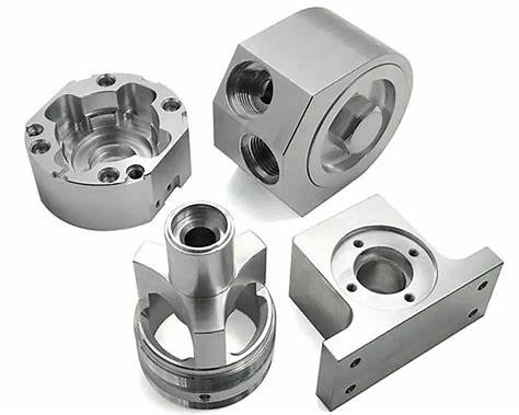
A hydraulic manifold is a block of metal whose internal passages replace a network of hoses, fittings and joints. That consolidation is what makes it valuable and what makes it demanding: an error inside the block cannot be seen, cannot be repaired, and will not appear until the system is pressurised. The machining decisions that matter are therefore made before the first cut, and they concern passage geometry, port sealing, cross-drilled intersections and cleanliness. This guide covers what manifold machining has to control and how to specify it.
What does manifold machining have to control?
Passage geometry, sealing surfaces and internal cleanliness.
The block has to route fluid through passages that are positioned accurately, seal at every port and connection, and be free of contamination that would damage components downstream.
Those three requirements drive the machining plan. Passage geometry determines the flow path and the wall thickness between channels, so the position and depth of every hole matters. Sealing surfaces, whether they are threaded ports, flat faces for O-rings or machined lands for cartridge valves, have to be flat and correctly sized, because a manifold leak is usually a sealing failure rather than a material one. And cleanliness determines whether the components the manifold feeds survive: a chip or a burr released into a hydraulic system damages pumps and valves that cost far more than the manifold.
The consequence for the specification is that a manifold drawing carries more information than most: passage positions with tolerances, port types and thread specifications, sealing face requirements, and a cleanliness requirement. Where a drawing is missing any of those, the machine shop is guessing about something that cannot be inspected after assembly.
How should passage layout be planned?
With wall thickness and intersection control.
Passages are drilled or milled into the block from several directions, and the wall thickness between adjacent channels determines both the strength and the risk of a breakthrough.
The layout starts from the circuit. Each function that the manifold replaces becomes a passage, and the passages have to connect in the right order while staying far enough apart that the walls between them tolerate the working pressure. The minimum wall thickness follows from the pressure, the material and the required safety factor rather than from a general rule, which is why the pressure rating belongs in the request.
Cross-drilling is how the connections are made. Two passages that meet at an angle create an intersection, and the intersection has a smaller effective wall area than either passage alone. Where several passages converge, that region is the most highly stressed part of the block and it also concentrates the chips and burrs produced by drilling, which is why it is both the most likely place for a leak and the hardest place to clean.
Depth control matters throughout. A passage drilled slightly too deep can break into an adjacent channel, which creates an internal leak that cannot be repaired; a passage that falls short of its intersection leaves the circuit open. That is why manifold programs specify depth and position tightly, and why the sequence of operations is planned so that each hole is drilled from a stable reference.
How do ports, threads and sealing methods work?
Each connection is a sealing system, not just a hole.
A port has to hold its component, seal at the working pressure and allow the connection to be made reliably, which depends on the thread, the sealing face and the component being fitted.
Threaded ports are the most common arrangement. The thread form and the sealing method work together: a port may seal on a tapered thread, on a machined shoulder with an O-ring, or on a flat face with a bonded seal, and each requires different preparation of the port. Tapered threads seal along the thread itself, while straight threads rely on a sealing face, so the two cannot be substituted without changing the port machining.
Sealing faces then have to be produced to a finish that the seal can work against. An O-ring seats in a groove whose depth and width control compression, and a face seal requires a flat, smooth land. Both are machined features with tolerances, and both are compromised by a scratch or a burr. Where a port is masked during a coating operation, the masking protects the sealing face as well as the thread, which is why masking requirements and port definitions belong on the same drawing.
Specialty ports, such as cavity ports for cartridge valves, add another dimension. The cavity has a defined geometry that the valve manufacturer specifies, and the machining has to reproduce it within a tolerance that allows the valve to seat and seal. Those cavities are normally produced with dedicated tooling, and the cavity specification comes from the valve supplier rather than being designed by the manifold machinist.
| Item | What it controls | Consequence if omitted |
|---|---|---|
| Working pressure | Minimum wall thickness between passages | Insufficient material at intersections |
| Passage positions | Whether the circuit connects as designed | Internal leaks or blocked functions |
| Port types and threads | Whether components fit and seal | Leaks or unusable connections |
| Sealing face requirements | Whether the seal holds | Weeping joints at pressure |
| Cleanliness requirement | Whether downstream components survive | Contamination damage in service |
| Test requirement | Whether the block is verified | Faults discovered after assembly |
How are cross-drilled intersections deburred?
From the inside, which is the difficulty.
Where two drilled passages meet, the second drill raises a burr inside the first, and that burr is on the side of the material that cannot be reached with a file.
The burr is not merely a cleanliness issue. It reduces the effective passage area at the intersection, it can break free later and travel through the system, and it creates a sharp edge that generates further debris. Because it sits inside the block, removing it requires either a mechanical method that can be introduced through the passages or a process such as abrasive flow, thermal deburring or electrochemical deburring.
The practical approach depends on the geometry and on the cleanliness requirement. Where the passages are accessible from the outside, manual deburring with a controlled tool can reach the intersection. Where they are not, a flow-based process circulates an abrasive medium through the passages, which erodes burrs and edges uniformly. Thermal deburring uses a brief, controlled combustion to oxidise thin edges, and it reaches intersections that no tool can access.
Whichever method is used, the burr removal step belongs in the process plan rather than in a note. A manifold that is machined accurately and deburred inadequately will contaminate its system, and the failure will appear in a pump or a valve rather than in the manifold itself.
Which materials are used for manifolds?
Aluminium for weight, steel for pressure and durability.
Aluminium blocks are light and machine quickly, while steel and stainless blocks are chosen for higher pressures, corrosive fluids or greater durability.
Aluminium is the common choice for mobile and moderate-pressure applications, where weight matters and the fluid is compatible with the material. It machines quickly, which keeps the cost of a complex passage layout manageable, and it takes a coating or anodized finish for corrosion protection. The grades available are listed on the aluminium machining materials page.
Steel and stainless steel are chosen where the pressure is higher, where the fluid is aggressive, or where the manifold also has a structural role. Both machine more slowly than aluminium, and stainless in particular requires more careful tooling and is prone to work hardening. The reward is higher strength and better corrosion resistance, which matters in marine, offshore and process applications.
Ductile iron and bronze appear in specific applications, usually where the manifold is part of a cast component or where the fluid requires a particular material compatibility. Where a casting is used as the starting point, the machined features are the ports and sealing faces, and the passage layout is created in the casting rather than drilled, which changes the manufacturing sequence entirely.
How is the machining sequence planned?
From stable references, with the critical features last.
The block is prepared first, the passages are drilled from datums that will not move, and the sealing faces and ports are produced last so that they are not disturbed.
The sequence starts with the block itself. Faces are prepared to establish datums, since every subsequent operation references them, and the block is squared so that passages drilled from different directions relate to each other correctly. Where the block will be heat treated or stress relieved, that happens before the final machining so that the dimensions are not disturbed afterwards.
Passages are then drilled and milled in an order that respects the intersections. Drilling a passage after an adjacent one has already been completed risks breaking into it at the wrong depth, so the sequence and the tooling are planned together. Where a passage has to intersect at a specific point, the program controls the depth and the operation is verified rather than assumed.
Ports, threads and sealing faces come last. They are the features that determine whether the manifold seals, and leaving them until the fixtures and datums are settled avoids the risk of re-clamping disturbing a finished seal face. Deburring and cleaning follow, then testing. The tolerance framework that governs those callouts is set out on 6CProto’s standards and tolerances page.
How is cleanliness controlled and verified?
By process, then by measurement.
Cleanliness is achieved through deburring, flushing and controlled handling, and verified by sampling the fluid that comes out of the passages.
The process controls come first. Burrs are removed by an appropriate method, the block is flushed to carry loose particles out, and the passages are capped or plugged for storage and transport so that contamination does not re-enter. Machining debris from a later operation, such as facing a sealing surface, has to be prevented from entering passages that were already cleaned, which usually means cleaning after the last operation rather than in the middle of the sequence.
Verification then measures what remains. A flush test collects the fluid passed through the manifold and counts or weighs the particles it carries, comparing the result with the cleanliness level the application requires. Where the requirement is strict, that test is part of the acceptance criteria rather than an optional check, and the level is stated in the specification.
Handling after cleaning matters as much as the cleaning itself. An uncapped manifold stored in a workshop will collect debris, and an assembly operation performed without covers will introduce contamination. Packaging that seals the ports and a procedure that keeps caps in place until final assembly are part of delivering a clean part.
What should be inspected and tested?
Dimensions, cleanliness and pressure integrity.
Inspection covers the passages that can be measured, the sealing faces and ports, and the cleanliness of the internal volume; testing confirms the block holds pressure.
Dimensional inspection focuses on what can be reached: passage positions at the surface, depths, port threads, sealing face flatness and the overall geometry that determines how the manifold mounts. Internal passages can be verified by gauging where the geometry allows, and by flow testing where the passage has a functional requirement.
Pressure testing is the check that confirms the block as a system. The passages are pressurised, individually or as a circuit, and the assembly is monitored for pressure loss or visible leakage. Where the manifold has to hold a specified pressure, the test pressure and duration come from the application requirement rather than from a general figure.
6CProto provides quality inspection reports on request and assigns a dedicated project manager to each order, so the inspection, cleanliness and test requirements can be agreed with the drawing rather than after delivery. The industrial applications that use these components are described on the industrial equipment industry page, and the quality practices behind that documentation are published by NIST MEP.
Specifying a manifold that works
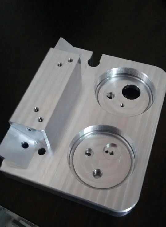
A manifold is the one component where a machining error may be invisible and unrecoverable, so the specification carries more weight than on most parts. The drawing should state the working pressure, the passage layout with positions and depths, the port and sealing specifications, the cleanliness requirement and the test that verifies the result. Those five items allow the machining sequence to be planned and the acceptance to be measured.
The practical habit is to involve the machine shop before the block is released for production, because a passage that cannot be drilled without breaking into a neighbour is a design problem rather than a machining one. Confirming the intersections, the wall sections and the deburring approach at that stage is faster than discovering an internal leak at pressure test. The materials available for manifold blocks are listed on the aluminium and steel material pages.
FAQ
What is the purpose of a hydraulic manifold?
It replaces a network of hoses, fittings and joints with passages machined into a single block, which reduces leak points, saves space and makes the circuit more repeatable to assemble. The manifold routes fluid between valves, pumps, actuators and reservoirs, and it carries the ports and sealing faces for the components that control the circuit. Consolidating the plumbing into a block is what makes a hydraulic system compact and serviceable.
What are hydraulic valve manifolds?
They are manifolds that carry the cavities and ports for directional, pressure and flow control valves, so that the valves mount directly onto the block rather than being connected by pipework. The manifold provides the passage network between them, and its cavities are machined to the valve manufacturer’s specification so that each valve seats and seals correctly. The result is a compact control assembly with far fewer external connections.
Why is cleanliness so important in a manifold?
Because the manifold feeds components that are far more sensitive to contamination than the block itself. Burrs left at cross-drilled intersections and particles trapped in passages travel through the system and damage pumps, valves and actuators, and the damage appears downstream rather than at the manifold. Cleanliness is therefore a functional requirement, verified by flushing and particle measurement rather than judged by appearance.
Can manifold passages be repaired if one breaks into another?
Generally not, because the leak is internal and the passage cannot be accessed. A passage drilled too deep may connect two circuits that have to remain separate, and that is a scrapped block unless the design has provision for a plug or a repair sleeve at a specific location. That is why passage positions and depths are specified tightly and why the sequence is planned to avoid drilling into a finished passage. The standards, materials data and regulatory framework referenced in this article are published by ASTM committee B08, ASTM D3359, ASTM committee D20, ASTM committee E28.
If a manifold has to hold pressure and feed sensitive components, send the model with the working pressure, the port specifications and the cleanliness requirement. 6CProto reviews manifold designs for manufacturability and returns a DFM report with the quote, so passage layout, wall sections and deburring are planned before machining. Upload the file at the 6CProto quote page or send it to projects@6cproto.com.