

A sheet-metal cover with countersunk screws sits proud on one side and pulls through on the other — the countersink depth varies with the sheet, the clearance hole is too tight in one spot and too loose in another, and the screws cannot seat consistently. Countersinks and clearance holes in thin sheet are easy to draw and easy to get wrong: the sheet is too thin for a standard countersink depth, the screw head needs a specific seat, and the clearance hole must accommodate the screw and the assembly tolerance without weakening the sheet. The dimensioning method is what makes the fastening reliable, and it starts with the screw type and the sheet thickness.
Countersink geometry in thin sheet: angles and depth limits
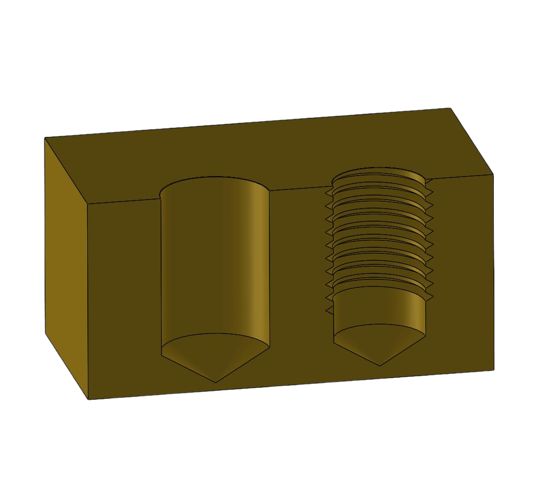
A countersunk screw seats in a conical hole that matches the screw head’s angle — typically 82 degrees for inch screws and 90 degrees for metric. The countersink depth in thin sheet is limited: the cone must be deep enough to seat the head flush, but the sheet must retain enough material around the hole to carry the load. In very thin sheet, a full-depth countersink can break through or leave a knife edge that tears. The design should check the screw’s head height against the sheet thickness, choose the countersink diameter and depth to seat the head, and confirm the remaining material is adequate. The countersink is specified by the angle, the diameter, and the depth, and the inspection verifies the screw seats as intended.
The head style matters as well: an 82-degree and a 90-degree head are not interchangeable, and the countersink should match the screw that the BOM specifies.
Screw clearance holes: charts and edge distance
The clearance hole must let the screw pass while the head or the fastener carries the load. The hole size follows the screw diameter with a clearance allowance that accommodates the assembly tolerance; a hole that is too tight jams the screw and fights the alignment, and one that is too large weakens the joint and lets the fastener shift. The edge distance — the material between the hole and the sheet edge — must be enough to prevent tear-out, and the spacing between holes must maintain the material between them. The clearance and edge-distance values come from fastening references, and the drawing should carry them for the critical joints rather than leaving the hole to the shop’s default.
The clearance hole also affects the countersink: a countersunk screw needs the clearance hole to align with the countersink cone, and the two features are dimensioned together.
Dimples and embosses: reinforcing thin sheet at fasteners
Thin sheet can be reinforced at the fastener by forming a dimple or an emboss around the hole. A dimple creates a conical depression that stiffens the area and provides more material for the screw seat or the fastener; an emboss raises the surrounding material to add stiffness and standoff. The formed feature adds strength without adding parts, and it is the design answer where the sheet is too thin for reliable fastening without reinforcement. The dimple or emboss geometry — the depth, the diameter, and the transition radius — is formed and carries its own tolerance, and the hole is often pierced after forming so the feature is not distorted. The reinforcement should be designed where the fastener carries load or the sheet flexes at the joint.
The forming adds a process step and the tooling to match, so the reinforcement is justified at the joints that need it, not applied to every fastener.
Failure modes: pull-through, tearing, and stripped heads
Sheet-metal fastening fails in recognizable ways. Pull-through happens when the screw head or the fastener pulls through the thin sheet, which points to an undersized head or an over-thin sheet. Tearing happens at the hole edge when the load or the assembly pulls against too little material, pointing to an undersized edge distance. A stripped head or a spinning screw points to the driver engagement or the thread fit. Each failure mode traces to a dimensioning decision, and the drawing should be reviewed against the failure the joint could see. The fastening is reliable when the head, the clearance, the edge distance, and the sheet thickness are matched to the load.
The review should also cover the assembly practice: the driver torque, the screw length, and the access that the assembly tool needs are part of the fastening design.
Matching screw type to sheet thickness
The screw type is chosen with the sheet thickness. Self-tapping screws form their own thread in the sheet but need enough material and the right pilot hole; machine screws need a threaded fastener or a nut on the back; and rivets or PEM fasteners provide the thread when the sheet is too thin. The screw’s head style, length, and thread must match the sheet and the joint. The drawing should specify the screw and the hole together, because the screw size sets the clearance and the countersink, and the sheet thickness sets the screw’s suitability. A joint that is designed as a system — screw, hole, countersink, and reinforcement — is a joint that assembles reliably the first time and every time.
The hardware and fastening guides on this site cover the fastener families; this page is the screw-into-sheet dimensioning decision. When the screw, the sheet, and the load are matched, the fastening is a designed feature rather than a field improvisation.
Verifying the fastening on samples
A fastening sample closes the design loop. A test panel with the specified screw, countersink, clearance hole, and edge distance is assembled and loaded to the service condition; the screw is checked for the seat, the pull-through resistance, and the tear-out margin; and the disassembly is checked for the service plan. The sample verifies the dimensions that the drawing carries and exposes the failures the calculation missed — a countersink that is too shallow for the head, a clearance hole that binds the screw at the tolerance extreme, or an edge distance that tears under the assembly load. The verification result becomes the standard for the drawing, and the sample is kept as the reference for the production inspection. A fastening design that is verified on the sample is a design that assembles reliably in production; one that ships from the calculation carries the risk into the field.
The verification should also cover the assembly variation: the screws from the specified supplier, the sheet from the production lot, and the torque from the production tool. The joint that works with one screw lot and one sheet lot can fail when the variation stacks, so the sample should test the tolerance extremes or the sample should be run with enough parts to confirm the margin. The inspection in production checks the features that the sample verified — the countersink, the clearance, and the edge distance — at the interval that catches the drift. When the fastening is verified and the production checks are set, the sheet-metal joint is a controlled feature, and the screws seat the same way on the production line as they did on the sample.
The countersink and clearance design should also be reviewed against the assembly sequence and the tool access. A screw that must be driven at an angle, a fastener in a pocket that the driver cannot reach, or a joint that is assembled in a sequence that covers the screw all fail in production even when the dimensions are right. The design should confirm the driver access, the assembly direction, and the service access, and the drawing should note the assembly constraints where the geometry is tight. The fastening is reliable when the dimensions and the assembly practice are designed together; a joint that is dimensionally correct but impossible to assemble is a joint that will be assembled wrong. The review that covers the tool access and the sequence is the review that produces fasteners that seat every time.
The countersink and clearance review should also check the finish and the coating, because a plated or painted sheet changes the hole and the screw fit. The coating on the countersink cone can change the seat depth, and the clearance hole can close with the coating thickness. The drawing should state the finish and the measurement basis, so the hole is punched or cut with the allowance. The finished hole that the screw seats in is the dimension that matters, and the specification should carry the coating with the hole.
Keep the fastening standard with the part: the screw, the hole, the countersink, and the edge distance, with the sample result. The standard makes the next revision and the next supplier start from the verified design, and it prevents the small changes that quietly weaken a joint. The standard is the drawing’s memory, and it is what keeps the fastening reliable across the product’s life.
If you are dimensioning countersinks and clearance holes for a sheet-metal part and want the screw, sheet, and edge-distance plan reviewed, the 6CProto sheet metal team can work from your fastener and load to the hole and reinforcement specification.