

Prototype parts get produced by printing, casting or molding, and the decision is usually made on speed and price. That is the wrong basis for it. Each route proves something different: printing proves geometry, casting proves form in a polymer that behaves roughly like a molded part, and molding proves the actual process that will make the product. This guide is written for product development teams that need validation parts and have to decide which route will answer the question their next decision depends on.
Should a prototype be printed, cast or molded?
Print for geometry, mold for process proof.
Printing is fastest and cheapest for form and fit, casting sits between the two, and molding in the production resin is the only route that also validates the manufacturing process.
The three routes differ in what they reproduce. A printed part reproduces the CAD geometry in a polymer whose properties depend on the printing process, so it validates shape, fit and assembly sequence but not the material. A cast part reproduces geometry in a polyurethane that can be formulated to approximate a production plastic, which makes it useful for appearance and some functional checks. A molded part reproduces the geometry in the production resin with the process that will make the product, which makes it the only route that validates shrinkage, gate placement and ejection.
Because of that, the routes are usually sequenced rather than compared. Printing resolves the design, casting checks appearance or produces a batch of near-production-feeling parts, and molding confirms that the design and the process work together. Programs that try to skip straight to molding often spend their first tool iteration on geometry problems that printing would have caught.
Where a decision has to be made quickly, the useful rule is to identify the single property the design depends on. If it is geometry, printing answers it. If it is material behaviour, molding does.
What does each route actually prove about the final part?
Geometry, behaviour and process, in increasing order.
Printing proves that the shape works, casting proves how a polymer part looks and handles, and molding proves that the design is manufacturable in the intended material.
Each route answers a category of question. Printing answers whether the assembly closes, whether the interfaces align, whether the user interface sits where the designer intended and whether the design can be manufactured at all in a general sense. Because the geometry comes directly from the model, it is also the fastest way to explore variants.
Casting answers questions about appearance and feel. A cast part can be produced in a polyurethane selected to approximate the stiffness or colour of the production resin, which makes it useful for design reviews, ergonomic evaluation and pre-production samples. What it cannot do is reproduce the flow behaviour, shrinkage or molded surface of the production process. The material systems behind those choices are documented by materials bodies such as ASM International.
Molding answers the manufacturing questions. Whether the part fills, where the weld lines fall, how much it shrinks, whether it ejects cleanly and whether the dimensions hold across a run are all molding questions. Where a program will eventually be molded, those questions have to be answered before the production tool is committed, and the prototype tool is where they get answered.
How far does material equivalence go?
Close for geometry, limited for behaviour.
A printed or cast part can match the production part’s shape and roughly its stiffness, but shrinkage, flow behaviour, surface finish and impact performance come from the molding process and the specific grade.
Material equivalence is where prototype programs most often deceive themselves. A printed part in a stiff polymer feels similar to a molded part in an engineering grade, but the printed part has directional strength, a different surface and no gate-related shrinkage. A cast part in a well-matched polyurethane can be closer in appearance, but its thermal behaviour and its fatigue response are not the production resin’s.
The practical test is whether the decision depends on the difference. For a fit check or a user trial, the difference is irrelevant, and printing is the efficient route. For a load case, a heat exposure or a drop test, the difference is the whole point, and the part should be molded in the production resin if the result is to mean anything.
Where a requirement has to be tested before molding is available, it is worth documenting the material actually used and treating the conclusion as indicative. The specifications that describe those differences, including the standard test methods for plastics, are published by ASTM committee D20, with mechanical testing defined by ASTM committee E28.
How does cost compare at 1, 25 and 200 units?
Printing wins small runs; molding wins large ones.
Cost per part falls as quantity rises in every route, but the fixed costs differ enough that the ranking changes with volume.
At a single unit, printing is almost always the cheapest route, because there is no tooling and the model is the only input. A cast part requires a master pattern and a mold, which adds fixed cost that a single unit cannot absorb. A molded part requires a tool, which is the largest fixed cost of the three.
At around twenty-five units, casting becomes competitive. The pattern and mold are amortised across the batch, and the cost per part falls accordingly. Printing remains viable, particularly for parts with complex geometry that would need several mold sections to cast, but the gap narrows and can reverse for simple parts.
At a few hundred units, molding starts to dominate. The tool cost is spread across enough parts that the low running cost takes over, and the parts are produced by the process that will make the product. That is the point at which the prototype tool becomes not just affordable but useful, because it also answers the manufacturing questions.
| Quantity | Usually the best route | What it proves |
|---|---|---|
| 1 to 5 | 3D printing | Geometry, fit, assembly sequence |
| 5 to 25 | Printing or casting | Geometry plus appearance and feel |
| 25 to 200 | Casting or a prototype tool | Appearance and, above the lower end, process behaviour |
| 200 and above | Prototype or bridge tool | Material, shrinkage, ejection and process window |
| Any quantity with a load case | Molding in the production resin | Behaviour that depends on the real material |
How do surface finish and appearance differ?
Molding reproduces the tool; printing reproduces the model.
A molded part carries the surface of the cavity, including its polish and texture, while a printed part shows the characteristics of its process and needs finishing to look molded.
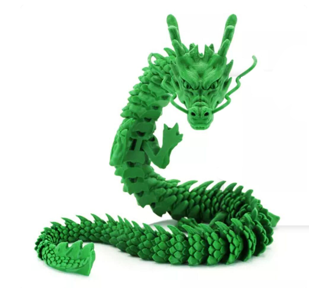
Appearance matters more than design teams expect, because the look of a prototype sets expectations for the product. A molded part in a polished cavity has a uniform, glossy surface with a subtle flow pattern near the gate. A printed part shows layer lines or a matte grain, and a cast part sits between, reproducing the master pattern’s surface while hiding the process marks. Where the finished part will be coated, adhesion and surface preparation follow documented test methods such as ASTM D3359.
Surface texture is also specified on the tool rather than on the part. Where a product requires a textured finish, that texture is produced by etching or machining the cavity, so the only route that validates it is molding. A printed part can approximate the appearance for a review, but it cannot confirm how the texture will read when molded into a specific resin.
Colour behaves similarly. Masterbatch or pre-compounded colour in the production resin behaves differently from dyeing or painting a printed part, particularly at edges and on textured surfaces. Where colour is a requirement, the molded part is the reference. Colourants, fillers and other additives are specified in the standards published by ASTM committee D20 on plastics.
When is mechanical testing on a prototype valid?
Only when the material matches.
A mechanical test is meaningful when the specimen is produced from the production resin by a process that gives comparable material behaviour, which generally means a molded part.
The reason is that polymer behaviour depends on thermal history and on flow orientation. A molded part has a skin, an oriented core and weld lines where flow fronts met, and those features influence strength and failure. A printed part has layer interfaces and directional properties that no molding process produces. A cast part has neither, but it is a different polymer.
That does not make testing on printed parts useless. It makes it a design check rather than a validation. Comparing two printed variants tells you which geometry is stiffer; it does not tell you whether the molded product will pass a drop test. Recording which of those two claims the test supports is what keeps the result honest.
Where a program needs to validate a structural requirement before tooling, the options are to mold a prototype tool early enough to test molded parts, or to test a machined sample of the production resin where the geometry allows. Both are more informative than testing a printed part and treating the result as representative. The test methods themselves are defined by ASTM committee E28 on mechanical testing.
How does the choice relate to the tooling decision?
The prototype route sets when the tooling decision is safe.
Printing and casting resolve design questions, while molding resolves manufacturing questions, so tooling should follow the route that answered the questions the tool depends on.
A production tool is committed on the assumption that the geometry is settled and the process works. Printing supports the first assumption: it confirms that the parts assemble and that the design is coherent. Molding supports the second: it confirms that the part fills, ejects and shrinks predictably in the intended material.
That is why the sequence usually involves a prototype tool even when the design has been printed many times. The prototype tool is not there to validate the geometry; it is there to validate the process, and the two validations happen in different processes for good reasons.
Where a program is under time pressure, the useful compromise is to run the prototype and production tool programs in parallel once the geometry is settled, using the prototype tool’s sampling to confirm the process window and the production tool’s design to incorporate those findings where possible. The risk in that approach is that a change identified during prototype sampling may arrive after the production tool is cut, so the program should decide in advance which findings would justify a tool change. The validation gates that structure those decisions are described in the 6CProto article on prototype validation gates.
Choosing the route that answers the question
Printing, casting and molding are not competing answers to the same question; they are three different tests. Printing tells you whether the design is coherent, casting tells you how a polymer part looks and feels, and molding tells you whether the product can be manufactured in the material it will be sold in.
The efficient program runs them in that order, stopping when the questions are answered. Where a design is still moving, printing iterations are cheap and fast. Where appearance or user feedback matters, casting produces convincing parts in modest quantities. And where the manufacturing decision has to be made, molding in the production resin is the only route that provides the evidence. The wider trade-offs between casting and molding at low volume are covered in the 6CProto article on urethane casting versus injection molding, and the manufacturing quality framework behind those decisions is published by NIST MEP.
FAQ
Is injection molding better than 3D printing for prototypes?
Neither is better in general; they prove different things. Printing is faster and cheaper and validates geometry, fit and assembly. Molding validates the material and the process, which is what a production decision depends on. Programs usually use both, printing to resolve the design and then molding to confirm that the design can be manufactured in the intended resin.
Is 3D printing a good way to make prototypes?
It is the most efficient way to explore geometry. A printed part comes directly from the model, costs little per iteration and can be produced in days, which makes it ideal for checking fit, proportion and assembly sequence. Its limitation is material behaviour: strength is directional and the resin is not the production polymer, so it cannot validate shrinkage or a load case.
How many prototype parts should be made before ordering tooling?
Enough to answer the questions the tooling decision depends on, which in practice means a printed set to confirm geometry, any appearance or user-testing parts needed, and a molded run in the production resin to validate shrinkage, ejection and the process window. The molded run should also produce a reference part and a dimensional report, since those become the standard for later production.
Can a printed prototype be used for a customer presentation?
It can, if surface finish and colour are representative and the audience understands the material. Printed parts often look more refined than a bare molded sample, which suits a design review. Where the product will be judged on weight, feel or texture, a cast or molded part with the production finish is the more honest demonstration and avoids setting expectations the final product cannot meet.
If the prototype route is still open, send the model with the question the parts have to answer and the resin you intend to produce in. 6CProto runs 3D printing, urethane casting and prototype injection molding in the same facility, so the routes can be compared from one manufacturing review. Upload the file at the 6CProto quote page or send it to projects@6cproto.com.