

Two prototypes of the same enclosure can look convincing and prove completely different things. A printed part validates form, fit and appearance quickly and cheaply; a formed metal part validates the material behaviour, the assembly method and the manufacturing route that the product will actually use. Choosing between them is not a question of which is better, but of which test the next decision depends on. This comparison sets out what each route can and cannot validate, how cost and lead time differ, and how to sequence both so that each one answers the question it is suited to.
Should a metal design be prototyped in metal or printed?
Both, in sequence, for most programs.
Printing validates form, fit and appearance cheaply; forming validates stiffness, assembly and manufacturability.
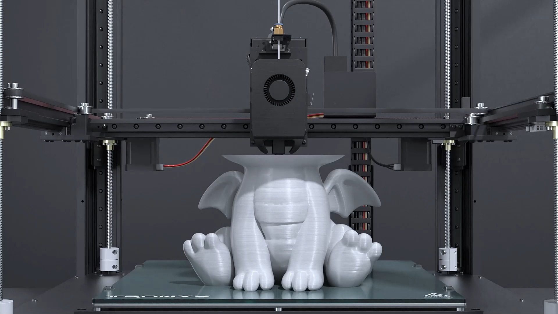
The reason to start with a printed part is iteration speed. A design change costs a new file rather than a new setup, and the printed model confirms that the geometry closes, that the interfaces align and that the shape reads the way the designer intended. That is a genuine test, and it removes a class of errors before any metal is cut.
The reason to move to metal before tooling is that the printed part cannot answer the questions that decide the production route. Whether a bracket is stiff enough in the chosen gauge, whether a hem can be formed without cracking, whether the assembly sequence works when the parts are rigid, and whether the flat pattern produces the intended geometry: all of these depend on the material and the process.
Programs that skip the metal prototype usually discover those issues at the tooling stage, where a change is expensive. Programs that skip the printed prototype usually spend their first metal iteration on errors that a model would have caught.
What can each process validate, and what can it not?
They validate different properties.
A printed prototype validates geometry, assembly and appearance; a sheet metal prototype validates material behaviour, forming limits, stiffness and the real assembly method.
The distinction follows from the materials. A printed prototype is made from a polymer, so its stiffness, weight and thermal behaviour are not representative of steel or aluminium. What it does represent faithfully is geometry: whether parts fit together, whether the design closes, whether a feature is reachable, and whether the assembly sequence is practical. Those are the questions that most often cause rework, and they are the ones a printed model answers well.
A metal prototype represents the material and the process. Stiffness and weight become real, the forming limits of the chosen gauge become visible, and the hardware and welding behave as they will in production. What it does not represent is the production tooling: a laser-cut and press-brake-formed part differs from a stamped one in edge quality, bend radius and repeatability.
| Question | 3D printed prototype | Sheet metal prototype |
|---|---|---|
| Does the assembly close? | Yes, with representative geometry | Yes, with real hardware |
| Is the part stiff enough? | Not representative | Yes, in the production material |
| Does the weight target hold? | Not representative | Yes |
| Can the bends be formed? | Not applicable | Yes, at prototype tooling limits |
| Is the appearance right? | Shape and proportion only | With the production finish applied |
| Does the production process work? | No | Partly; tooling behaviour still differs |
How do dimensional behaviour and stiffness compare?
Geometry transfers; stiffness does not.
A printed part reproduces the shape but not the mechanical behaviour of sheet metal, so a design judged adequate in polymer may be over- or under-built in the production material.
Stiffness in a formed metal part comes from the material’s modulus, the gauge and the geometry that bending creates. A printed polymer part has a different modulus by an order of magnitude, and its stiffness also depends on print orientation and internal structure, none of which exists in the sheet metal part. The practical consequence is that a printed prototype cannot validate a load case, and a metal prototype cannot be replaced by a printed one for structural testing.
Dimensional behaviour is closer but still differs. A printed part holds the geometry of the CAD model with printed tolerances; a formed part holds the geometry of the flat pattern with bend variation. That means a printed model is useful for checking hole positions in the design intent, while a formed prototype is needed to confirm where those holes actually land after bending. The forming behaviour behind that difference, including how each alloy springs back, is documented by materials bodies such as ASM International.
Where a program needs both, the sequence is straightforward: use the printed model to confirm the design, then the metal prototype to confirm the dimensions after forming and the behaviour under load.
How do assembly, welding and hardware behave differently?
Metal assembly is the part that printing cannot test.
Welding distortion, fastener insertion and the sequence of tightening all depend on the material and hardware, so a printed prototype cannot validate an assembly method.
Assembly is where the difference is most visible. Stacking printed parts proves that the geometry is compatible; assembling formed parts proves that the process is practical. A weld pulls the parts together slightly as it cools, which changes the alignment of everything else. A self-clinching fastener needs a hole of the correct size and enough material around it, and installing it in a prototype reveals whether the design provides that. And a sequence that works on a bench with three printed parts may not work when the components are heavier or when access is restricted by rigid panels.
Hardware specification also becomes concrete. The prototype confirms whether a captive screw sits flush, whether a rivet nut can be set without deforming the panel, and whether a hinge line aligns after forming. Those are inexpensive checks at prototype stage and expensive after tooling.
Where welding is part of the design, the prototype should include it, because the distortion and the finishing work it requires are part of the manufacturing cost and the schedule. The fabrication route that supports those operations is described on the sheet metal fabrication page. Where a coating is applied afterwards, adhesion and surface preparation follow documented test methods such as ASTM D3359, and any chemical waste from a plating or coating line is handled under the industrial framework published by the US Environmental Protection Agency.
How do cost and lead time compare at each stage?
Printing is cheap per iteration; metal is cheap per proof.
A printed iteration costs a file and a build, while a metal prototype costs cutting, forming and hardware, so the useful strategy is to iterate in printing and to spend on metal only when the design is stable.
The cost structure explains the sequencing. A printed part is produced from the model with almost no setup, so a design change costs little and several iterations can be run in the time a metal prototype would take to schedule. That makes printing the right tool for exploring geometry, testing proportions and resolving fit issues.
A metal prototype carries setup in cutting, forming and hardware insertion, and each of those steps has a queue. Running it after the geometry is stable means the metal part is spent on validating the questions that printing cannot answer, rather than on rediscovering a fit error.
Lead time behaves the same way. Printing iterations run in days, and metal prototypes depend on the shop’s capacity for cutting and forming. Where a program has a fixed review date, the sequence of two printed iterations followed by one metal prototype usually fits better than two metal iterations.
How should the two be sequenced?
Print for geometry, then fabricate for behaviour.
A practical sequence is a printed form-and-fit model, a revision, then a metal prototype in the production material and gauge that is inspected and used for the design sign-off.
The first printed iteration answers the questions that must be resolved before anything else: does the assembly close, do the interfaces align, is the shape right, and does the design create any obvious manufacturing problem. It is also the cheapest moment to change the design.
The second stage moves to metal. The prototype is cut and formed in the production material and gauge, hardware is installed, and the part is checked against the interfaces that decide assembly. Where the design includes welding, it is included here, because weld distortion is a real effect that the prototype is meant to expose.
The third stage is documentation. Dimensional results from the metal prototype become the reference for tooling, and any deviation becomes a design decision rather than a surprise later. That handover is what makes the prototype worth its cost, and it is the reason the inspection scope should be agreed before the part is made.
Where a program is under time pressure, a useful compromise is to print the parts that are geometrically complex and fabricate the ones that carry load or form a critical interface. The mixed approach captures most of the value of both routes at a fraction of the cost of doing everything twice. The terminology that separates prototyping from additive manufacturing in these discussions is explained in the 6CProto article on rapid prototyping and additive manufacturing.
Which prototype de-risks the tooling decision?
The metal one, inspected and documented.
Tooling decisions depend on whether the design can be formed repeatably at the intended gauge, which is a question only a metal prototype can answer.
Where a program will move to stamping or to a dedicated forming setup, the prototype’s role is to confirm the design before that investment. The features that decide it are bend radii, relief and notch geometry, hole sizes relative to material thickness, and the flat pattern that the shop generates. A printed part cannot confirm any of them.
The prototype also establishes the acceptance criteria. Once a metal part has been measured and accepted, the same features and the same method become the basis for the production inspection plan, which removes the ambiguity that otherwise appears when a tool is first sampled.
Where the prototype reveals a problem, that is a success rather than a setback. A bend that cracks, a relief that is too small or a fastener that cannot be set are all cheaper to fix on a prototype than on a tool. The value of the exercise is measured by what it prevents, not by whether the first attempt was perfect. The engineering context for those manufacturing decisions is published by ASTM committee B08 for coating and surface subject matter, with broader manufacturing guidance from NIST MEP.
Choosing the sequence that fits the program
Printing and sheet metal prototyping are complements, not alternatives. Printed parts are the fast, inexpensive way to resolve geometry, and formed metal parts are the only way to validate stiffness, weight, hardware and manufacturability in the production material. Sequencing them, print first and fabricate once the design is stable, captures both benefits and spends the metal prototype on the questions that only it can answer.
The specification work that makes the sequence effective is small. Decide what each prototype is for, keep both in the same design revision, and ask for dimensional results from the metal part on the features that decide assembly. Those three habits turn two prototypes into evidence for the tooling decision instead of two models on a shelf. The wider prototyping scope is described on the rapid prototyping page.
FAQ
Is 3D printing good for prototyping sheet metal parts?
Yes, for the questions printing can answer. A printed model is an effective way to check that an assembly closes, that interfaces align and that the shape is right, and it costs far less per iteration than a formed part. What it cannot do is validate stiffness, weight, forming limits or hardware behaviour, because the material and the process are different. Use it to stabilise the geometry, then confirm the design in metal.
What are the disadvantages of prototyping in printed plastic?
The mechanical and thermal behaviour is not representative of sheet metal, so load cases, weight targets and stiffness cannot be validated. Forming behaviour is absent entirely, which means bend radii, relief geometry and springback remain untested. And assembly realism is limited, because welding and fastener insertion behave differently on a polymer part. For form and fit, none of that matters; for the manufacturing decision, all of it does.
Can a printed prototype be used for a customer presentation?
It can, provided the surface finish and colour are representative and the audience understands the material. A printed model often looks more refined than a bare metal prototype, which is an advantage for design reviews. Where the product will be judged by its weight, its feel or its finish, a metal prototype with the production finish is the more honest demonstration, and it avoids setting expectations the final product will not meet.
How many prototypes should a program make before tooling?
Enough to resolve the questions that would be expensive to fix later. In practice that is usually one or two printed iterations to stabilise geometry, followed by one metal prototype in the production material that is inspected and documented. Programs that need more iterations are usually still changing the design rather than validating it, and the schedule saving comes from resolving design questions in the cheaper process.
If a metal design needs a prototype that actually informs the tooling decision, send the model with the interfaces that must line up and the gauge you intend to use. 6CProto runs sheet metal fabrication and 3D printing in the same facility, so both stages can be planned as one sequence with a single manufacturing review. Upload the file at the 6CProto quote page or send it to projects@6cproto.com.