

Sheet metal prototypes are quick because nothing is tooled: the flat pattern is cut, formed and finished with general-purpose equipment. The interesting question is not how to make the first bracket but at what quantity that approach stops being the sensible one.
How the process route changes with quantity
At prototype quantities, laser cutting produces the blank and a press brake forms it, with hardware inserted or riveted afterwards. As volume grows, two things change: blanking moves toward punching or a dedicated die because it becomes faster per part, and forming moves toward dedicated tooling where the bend sequence is fixed rather than set up each time. The switch points are not fixed numbers; they depend on part geometry, the number of bends and how much setup time the shop has to absorb.
| Stage | Cutting | Forming | What changes at the handover |
|---|---|---|---|
| Prototype | Laser cut from flat sheet | Press brake with standard tooling | No tooling cost; setup time per part is high |
| Pilot batch | Laser or turret punch | Press brake with a fixed programme | Consistent bend sequence; less variation between parts |
| Production | Dedicated die or progressive tool | Dedicated forming tooling | Tooling cost amortised; tighter repeatability |
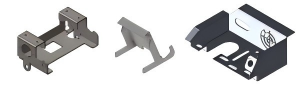
Why the switch point is a design question, not a volume question
Because geometry decides how much setup is repeated.
A simple bracket with two bends accumulates very little setup time per part, so laser cutting and brake forming remain competitive much further into the volume curve than a part with eight bends, several hardware inserts and a cosmetic finish. The same logic explains why a part with one hand-adjusted operation has a lower switch point than its overall quantity suggests.
Where a part family is expected to repeat, the decision shifts again. A fixture or a simple forming tool that can be reused across several brackets earns its cost over a family rather than over a single part number, which is why it is worth telling a supplier that more parts are coming rather than quoting one in isolation.
What tolerance a formed prototype can hold
Formed sheet metal behaves differently from a machined part, and the drawing should reflect that. The bend radius, the springback of the material and the position of the bend line all move the finished geometry, so cumulative tolerances across a series of bends add up in a way that a single machined face does not. Holes placed near a bend are the most common source of assembly problems, because the material stretches differently on each side of the neutral axis.
The practical answer is to control what the assembly reads and let the rest follow the general note. Hole positions used for fastening, the overall envelope, and any face that carries a mating surface deserve individual callouts; the rest of the profile can be governed by a general tolerance. Guidance on drawing conventions for formed parts follows ASME standards, and measurement practice for these features is described by the NIST Manufacturing Extension Partnership.
Bend design detail that prevents rework
Four details prevent most sheet metal prototype rework. A hole or slot should sit at least a material thickness clear of a bend line, or it will distort when formed. Internal corners should carry a relief so the material does not tear. The bend radius should be at least comparable to the material thickness, because a tighter radius cracks the outer fibres on harder grades. And the flat pattern should be developed with a consistent K-factor, since the same part developed with two different assumptions produces two different blanks.
Hardware is the other common source of scrap. Pressed inserts, standoffs and clinch nuts need a clear area on both faces and enough edge distance that the sheet does not deform around them. Specifying them before the flat pattern is finalised avoids a batch that is dimensionally correct but cannot accept its fasteners. Related process detail is collected on the forming and bending and laser cutting pages.
Finishing, and how it interacts with forming
Finishing is usually applied after forming, and that order matters. Anodizing, powder coating and plating all add or remove material, and a pressed insert fitted before coating may no longer accept a mating part afterwards. Masking is available but it is a handled step with its own cost, so the cheaper route is to place hardware after finishing where the design allows it.
Cosmetic requirements also interact with the process. A brushed or grained finish applied before bending shows witness marks along the bend, so the grain direction and the forming sequence should be chosen together. Coating classifications follow ASTM Committee B08, environmental obligations for coating and cleaning lines are published by the US EPA, material behaviour data comes from ASM International, and drawing conventions from ASME. Assemblies that combine several formed parts are covered under fabricated assemblies.
What to send with a sheet metal prototype request
A formed part is quoted from three things: the flat pattern or the formed model, the material and thickness, and the hardware list with its positions. Adding the quantity, the finish and any assembly the part belongs to turns a price for a blank into a price for a part that can be installed. Where the flat pattern has not been developed yet, saying so is better than sending a model with a guessed K-factor, because the blank is what the cutter actually needs.
Two notes prevent rework. Mark the cosmetic faces, so grain direction and finishing sequence can be planned around them, and name the features that must locate an assembly, so tolerances are concentrated where they matter. The remaining profile can follow a general tolerance, which keeps the part affordable without risking the fit. Related process detail sits under laser cutting and forming.
Send the flat pattern or the formed model with your quantity and hardware list, and request a sheet metal prototyping quote.
FAQ
How many sheet metal parts justify dedicated tooling?
There is no single number, because setup time per part depends on the bend count and the hardware operations. A simple bracket stays economical on laser and brake for much longer than a part with many bends and inserts.
What tolerance can a bent sheet metal prototype hold?
Bend-angle and position tolerances accumulate across a series of bends, so cumulative error grows with the bend count. Controlling the features the assembly reads, and letting the rest follow a general note, keeps the part affordable and measurable.
When does laser cutting stop being the right cutting method?
When blanking time per part becomes the limiting cost rather than setup. At that point punching or a dedicated die becomes faster per piece, and the decision turns on the tooling cost against the expected quantity and the life of the design.