
Sheet Metal Prototyping
Turn CAD designs into functional sheet metal prototypes for form, fit, assembly, design validation, and pre-production testing. 6CProto combines laser cutting, punching, forming, bending, fabricated assemblies, finishing, and DFM support to move designs from concept toward production.
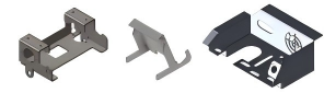





Rapid Sheet Metal Prototypes for Design Validation
Sheet metal prototyping converts a digital design into production-representative metal parts quickly enough to support iteration. It is used to evaluate form, fit, function, fastener locations, bend behavior, assembly sequence, strength, appearance, and manufacturability before production is finalized.
This page focuses on rapid prototypes and low-volume validation. Use sheet metal stamping when stable production demand justifies punch-and-die tooling, sheet metal welding for joining-focused assemblies, or tube fabrication for tubular structures.
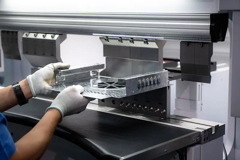
Explore Sheet Metal Prototyping Resources
Jump directly to process, capabilities, materials, applications, design guidance, quality controls, or FAQs.
What a Sheet Metal Prototype Can Validate
A useful prototype should answer specific engineering questions rather than only reproduce the nominal CAD shape.
Form and Fit
Check envelope, interfaces, clearances, holes, bends, hardware, and mating components.
Functional Testing
Evaluate stiffness, handling, assembly behavior, mounting, access, and service requirements.
Appearance Review
Assess visible seams, edge condition, finish, texture, color, and cosmetic faces.
Pre-Production Learning
Identify DFM changes before repeat orders or production tooling are committed.
Rapid Sheet Metal Prototyping Workflow
The workflow follows the existing 6CProto upload, DFM, manufacturing, finishing, inspection, and shipping process.
Submit CAD and Drawing
Provide the model, flat or formed drawing, material, thickness, quantity, hardware, finish, and critical requirements.
Review Manufacturability
Engineers review cutting, bend radii, hole-to-bend distances, reliefs, welding, hardware, tolerances, and finish.
Cut, Form, and Assemble
Parts move through the approved laser cutting, punching, forming, bending, welding, or assembly route.
Inspect and Deliver
Prototype dimensions and appearance are checked before finishing, packing, and shipment.
Sheet Metal Prototyping Capabilities
Prototype process selection is based on the flat blank, bends, formed details, joints, hardware, finish, and required learning.
| Published Process | Published Planning Value | Prototype Use |
|---|---|---|
| Laser Cutting | Sheet up to 3000 × 1500 mm; typical ±0.1 mm | Flat blanks, panels, plates, cutouts, and profiles |
| Published Laser Thickness | Steel up to 20 mm; aluminum up to 12 mm; stainless up to 10 mm | Final capability depends on material, geometry, and finish |
| Punching | Mild steel up to 3.0 mm; typical ±0.2 mm | Repeat holes, slots, and tooling-compatible features |
| Forming and Bending | Bend length up to 3000 mm; thickness up to 6 mm; typical ±0.3 mm and angle ±1° | L, U, Z, and multi-bend prototype parts |
| Fabricated Assemblies | By design; published fit-up guidance ±0.5 mm | Welding, hardware insertion, finishing, and assembly |
Materials and Finishes for Sheet Metal Prototypes
Select a production-relevant material and finish when the prototype must provide meaningful form, function, or appearance feedback.
Aluminum
Listed grades include 5052, 5083, 6061, and 6082 for lightweight prototype panels, brackets, housings, and assemblies.
Stainless Steel
Listed grades include 301, 304, and 316 for corrosion-resistant and appearance-sensitive prototypes.
Steel
Published sheet categories include 1018 and SPCC for strong, cost-effective functional prototypes.
Copper
Listed copper grades include 101 and C110 for conductive, thermal, and visual prototype components.
Brass
Listed brass grades include C26000 and C10100 for decorative, electrical, and functional prototype parts.
Finish Selection
Choose from compatible website-listed options such as deburring, bead blasting, anodizing, Alodine, polishing, brushing, black oxide, plating, and passivation.
Design Guidelines for Sheet Metal Prototypes
The design should allow rapid fabrication while preserving the features needed for meaningful validation.
Prototype-Friendly DFM
- Use one consistent thickness where practical.
- Choose realistic internal bend radii.
- Keep holes and slots away from bend deformation zones.
- Add reliefs where bend lines intersect edges or features.
- Use accessible hardware and joining locations.
- Identify cosmetic faces and finish requirements.
Submit a Complete RFQ
- Provide both the 3D model and dimensioned drawing.
- State material grade, thickness, and quantity.
- Identify critical dimensions and general tolerances.
- Include PEM hardware, weld symbols, and assembly BOM.
- State the test objective and expected production process.
- Mark acceptable prototype deviations if speed is the priority.
Quality Assurance for Sheet Metal Prototypes
Prototype inspection should concentrate on the dimensions and characteristics that drive the next design decision.
DFM and Drawing Review
Material, flat pattern, bends, reliefs, holes, hardware, welds, tolerances, and finishes are reviewed before fabrication.
In-Process Checks
Cut parts, formed geometry, fit-up, hardware, and assemblies are checked at appropriate stages.
Prototype Inspection
Final inspection is matched to the validation goal, drawing requirements, critical dimensions, and requested reporting.