

A 3D printed housing looks smooth in the vendor’s sample photo and arrives with visible layer lines and a grainy texture. The vendor did not ship a bad part; the buyer specified “smooth finish” without defining the process, the orientation, or the acceptance sample — and every printing process leaves a characteristic surface that post-processing changes in its own way. Surface finish on printed parts is a specification problem: the drawing should say which finish class is needed, which process produces it, and how the part will be judged.
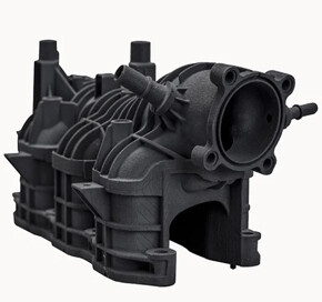
What “as-printed” actually means for SLA, SLS, MJF, and metal
Every process leaves its own surface signature. SLA parts show layer lines from the print, with a smooth resin base that post-processing can polish toward clarity. SLS and MJF nylon parts have a grainy, matte surface from fused powder, and MJF typically shows a finer texture than SLS on the same geometry. Metal printing leaves a rough, partially sintered surface that is often bead-blasted or machined where function demands. “As-printed” is not one finish; it is a range that depends on the process, the layer height, the orientation, and the machine.
That range is why the drawing should not say “as-printed acceptable” without stating the process and the acceptance sample. If the part is a prototype that only checks fit, the as-printed surface may be fine; if it is a cosmetic housing or a sealing surface, the as-printed surface is only the starting point.
How orientation and layer height set your starting finish
Orientation decides where the layer steps appear. A face printed flat on the build plate has a different texture than a face built vertically, where every layer edge is visible; curved surfaces and shallow angles create their own step patterns. Layer height sets the step size, so a thinner layer improves the finish at the cost of build time. The functional surfaces should be oriented to minimize visible stepping where appearance matters, and the layer height should be stated when the finish class depends on it.
Support contact is the second orientation effect: faces that carried supports show marks after removal, and the mark depends on the support density and the removal method. If a surface must be clean, keep supports off it or plan the post-processing that removes the marks. The print orientation is a finish decision, not just a cost decision.
Post-processing options mapped to roughness and appearance goals
Post-processing is where the finish is actually made, and the options map to different goals. Sanding reduces layer lines but changes dimensions and can round edges; vapor smoothing on nylon closes the surface texture but alters small features and can change fit; dyeing adds color to SLS/MJF parts but does not change texture; clear coating or polishing serves SLA clarity; and metal parts are bead-blasted, machined, or coated depending on the function. Each step has a cost and a dimensional effect, and the drawing should name the finished state, not just the process family.
| Process | Finish result | Watch out for |
|---|---|---|
| SLA + polish/clear coat | Smooth, can approach transparent | Dimensions change; edges round |
| SLS/MJF + vapor smooth | Closed, semi-gloss surface | Small holes and fits can close |
| SLS/MJF + dye | Uniform color | Texture unchanged; color varies by lot |
| Metal + bead blast | Uniform matte | Removes surface texture but not all roughness |
| Metal + machining | Precision surface on critical faces | Planned as a separate operation with stock |
The table is a mapping tool for the finish review: identify the goal, choose the post-process, and check the dimensional effect before the drawing is locked.
Specifying finish on drawings without overpaying
Write the finish as a class tied to function, not as a vague adjective. “Smooth” is not a specification; “texture comparable to the approved sample, no visible layer steps on the front face” is closer, and a numeric roughness value with the measurement direction is better where a surface is truly functional. Restrict the finish requirement to the surfaces that need it: a cosmetic front face may justify post-processing while hidden faces stay as-printed, and requiring a smooth finish on every surface is the most common way to overpay on printed parts.
Ask the vendor what its standard finish includes and what each upgrade costs, because “standard” differs between services. A part quoted at one service may include dyeing or light sanding that another service charges as an option; the comparison only works when the finish scope is identical.
Acceptance samples: agreeing on texture, color, and witness lines
Printed surfaces are best judged against a physical sample, because words and numbers do not capture texture. Keep an approved sample of the finish class — texture, color, and allowed witness lines — and inspect production parts against it under defined lighting. If the finish is numeric, measure it with the method stated on the drawing; if it is cosmetic, the sample is the standard and the lighting condition matters.
Color on printed nylon is a special case: dyeing is consistent within a batch but can vary between batches and materials, so a color tolerance should reference a sample or a standard, not a name. The acceptance sample is also the record for the next order: without it, the second batch can match the first vendor’s sample while failing your memory of the first delivery.
A finish-decision example ties the rules together. A handheld device housing is printed in nylon for a pilot run of fifty parts. The front face is cosmetic, the side faces carry a sliding fit with the battery door, and the interior is hidden. The drawing marks the front face “texture per approved sample, no visible layer steps,” the slide rails “fit verified with the mating part,” and everything else “as-printed acceptable.” The supplier orients the part so the front face carries the best surface, plans vapor smoothing only on the front and the rails, and quotes the interior as-printed. The pilot parts match the sample on the visible face, the slide rails are checked against the mating part after smoothing, and the buyer pays for post-processing on exactly the surfaces that need it instead of on the whole part. The alternative — “smooth finish” with no location, no sample, and no process — produces a part that is over-processed or under-processed depending on the supplier’s interpretation, and a second batch that does not match the first. The acceptance sample and the marked drawing remove the interpretation, and the inspection is a comparison to a physical standard rather than a judgment of a word. That is how printed finishes are specified: functionally, visually, and measurably, with the cost attached to the surfaces that earn it.
The finish specification checklist: mark the cosmetic faces and the functional surfaces on the drawing; state the finish class with the sample reference; name the post-process only where the result depends on it; note the measurement method if the finish is numeric; and confirm the dimensional effect of post-processing on fits. When the pilot parts arrive, compare them to the approved sample under the defined lighting before the design is frozen, because the sample is the standard the production parts will be judged against.
Keep the finish records with the order: the approved sample, the process notes, the layer height and orientation, and the measured result on functional surfaces. When the next order is placed, the records make the finish repeatable without re-negotiating the standard — and when a batch arrives looking different, the record shows whether the process changed or the expectation did.
Frequently asked questions
Can 3D printed parts be polished to a mirror finish?
In some cases. SLA parts can be polished and clear-coated toward a glossy or transparent result, and nylon parts can be smoothed, but a true mirror finish is not typical for printed polymers. Metal printed parts can be machined and polished on selected faces. Define the target with a sample before committing, because “mirror” means different things to different shops.
Does vapor smoothing change dimensions?
Yes. Vapor smoothing melts and reflows the surface layer, which closes texture and can shrink or round small features. Parts with tight fits should be smoothed with allowance or post-machined, and the dimensional effect should be validated on samples rather than assumed.
How do you measure roughness on a printed part?
With the same discipline as machined parts: state the parameter, the standard, the measurement direction, and the area. Printed surfaces are not isotropic, so the direction matters even more, and textured or smoothed surfaces may need a visual or sample standard rather than a single Ra number.
The finish that fits the function
Printed surface finish is controlled by orientation, layer height, post-processing, and acceptance samples — and the drawing should specify all four where the finish matters. Save the smooth finish for the surfaces that need it, define the finished state instead of the process family, and judge against a sample. The part that looks right on arrival is the one whose finish was specified before the file was sent.

If you are specifying a printed part with a visible or functional surface, the 3D printing team can review the finish class and post-process plan against your geometry before quoting.