

A supplier’s inspection report shows Ra 0.8 μm on a sealing face, and the assembly leaks. The buyer re-measures the same face and gets Ra 1.6 μm. Neither measurement is wrong: one report used a 0.8 mm cutoff, the other used 2.5 mm, and the two cutoffs filter different wavelengths into the roughness calculation. Surface roughness looks like a simple number, but Ra, Rz, cutoff, sampling length, and tracing direction all change the result. Understanding what each parameter measures — and how the instrument is set up — is the difference between a roughness spec that is verifiable and one that produces arguments at every inspection.
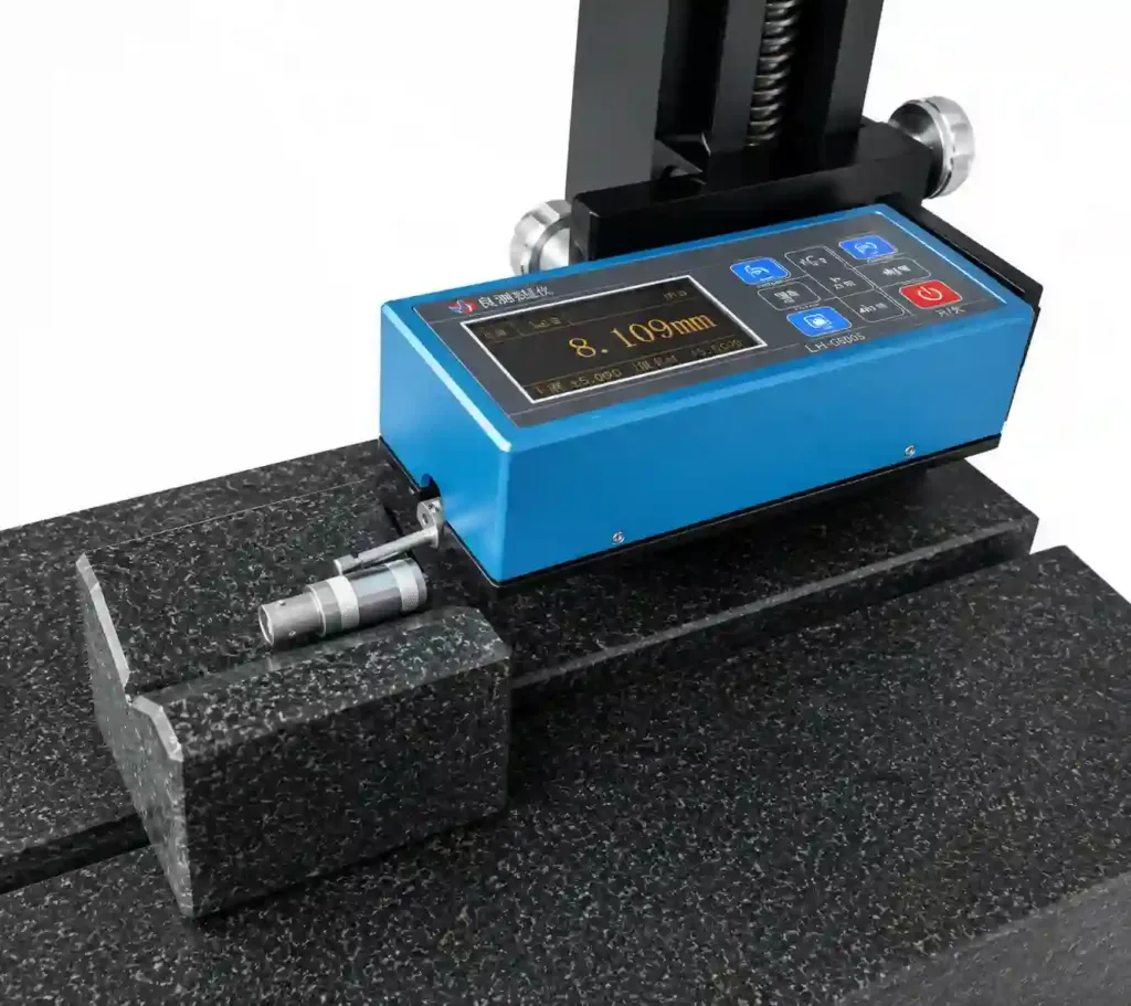
Ra averages the surface; Rz catches the extremes
Ra is the average deviation of the surface profile from its mean line: it smooths the whole trace into one number, which makes it stable and easy to compare. Rz is an extreme-height parameter whose exact calculation depends on the standard in force — modern ISO profile analysis (the ISO 21920 series) and ASME B46.1 define evaluation length and height evaluation differently from older DIN-style methods. A surface can have the same Ra and very different Rz, because Ra averages out a scratch that Rz catches.
Choose the parameter by the function. If the requirement is consistent finish class or coating adhesion, Ra is usually enough. If the requirement involves sealing, bearing contact, or a single deep tool mark, Rz or a related extreme-value parameter is closer to the real failure mode. The drawing should name the parameter, because “finish 0.8” is ambiguous and the shop will default to Ra.
Cutoff, direction, and tracing length change the number
A profilometer traces a stylus along the surface and separates the profile into roughness and waviness using a cutoff wavelength. The cutoff defines what is counted as roughness: a short cutoff treats longer waves as waviness, while a long cutoff includes them in the roughness value. The sampling length, the stylus geometry, and the tracing speed also affect the result, which is why two instruments on the same surface can disagree.
Direction matters even more on machined surfaces, which are not isotropic. A trace perpendicular to the tool path crosses the feed marks and reads higher roughness; a trace parallel to the path rides along them and reads lower. If the drawing does not state the direction, the supplier will choose the favorable one, and the sealing face will be specified in name only. State the direction on the drawing or in the inspection note.
Ra-to-Rz conversion is an approximation, not a rule
Rough conversion relationships exist for typical machined profiles — a common rule of thumb for ground and turned surfaces is Rz of roughly four to seven times Ra — but they are approximations, and they fail on textured, honed, coated, or anisotropic surfaces. Converting a specification because one side measured the other parameter invites the exact dispute described above. When the drawing says Rz, request an Rz measurement; when the supplier reports Ra, ask why, and require the parameter to match.
| Surface condition | Why conversion is risky |
|---|---|
| Ground or turned | Ratios hold only for typical profile shapes |
| Honed or plateaued | Peaks and valleys differ from average; Rz and Ra diverge |
| Coated or plated | Coating changes peaks and valleys unevenly |
| EDM or textured | Non-uniform profile makes any ratio unreliable |
The safe comparison is the same parameter, the same cutoff, and the same direction. If the report does not state the cutoff and direction, the value cannot be compared to the drawing, and the inspection has not actually verified the requirement.
A drawing callout carries parameter, value, area, and direction
Write the parameter with its unit, the value, the area of application, and the direction: “Ra 0.8 μm on the sealing face, direction parallel to the bore axis” is a spec; “Ra 0.8” on a general note is a guess that mixes unitless numbers and leaves the standard open. Add the cutoff where the surface is unusual, and state when roughness applies before coating, because plating and anodizing change the measured surface. If the surface must not be touched or measured in a particular area, say so; the inspector will measure where the drawing directs.
Roughness and waviness are different requirements. A surface can meet Ra and still leak because long-wave waviness prevents the gasket from seating; if the function needs flatness or waviness control, write those callouts separately instead of hoping the Ra number covers them. Choose and state the standard the drawing follows — the ISO 21920 series or ASME B46.1, for example — and remember that legacy drawings may reference ISO 4287 or older DIN definitions, so the standard version must be checked before comparing values. The drawing and the report should both name the standard, the filter or cutoff, the evaluation length, and the stylus tip radius, because Rz values from different standards and settings are not directly comparable. Rz also is not always the best parameter for one isolated scratch: a single deep event may need Rt, a maximum-defect limit, or an appearance standard rather than an average-of-heights value. The standards and tolerances section of this site explains how to write finish and form requirements so they are measurable.
How do you verify a roughness report from the shop?
Check the essentials before accepting a report: the parameter matches the drawing, the value is in range, the cutoff is stated, and the measurement location matches the functional surface. Ask how many traces were taken; a single trace on a machined surface can miss the variation along the tool path. For critical seals and bearings, keep the sample and repeat the measurement at the same location if there is any doubt, because roughness is measured in micrometers and small setup differences matter at that scale.
If the shop and the buyer use different instruments, compare methods before comparing values: same cutoff, same tracing length, same direction. A calibration check with a known roughness standard resolves most disputes faster than re-measuring the part, because the disagreement is usually in the setup, not in the surface.
Roughness specifications also need to account for where the surface came from. A turned face, a milled face, and a ground face produce different profile shapes at the same Ra, and a specification written for one process can mislead when the process changes. If a sealing face is switched from ground to turned, the Ra value may be held while the Rz and the lay direction change, and the seal can fail even though the average number looks the same. The drawing should state the required process or, better, the functional parameters — including the lay direction when it matters. Surface roughness is also measured on the finished surface: plating, anodizing, and coatings change the profile, so a roughness callout that applies before coating must say so, and the coating thickness must not be used to mask a rough substrate. When a supplier proposes a process change that affects the surface, treat it as a specification change and re-verify the roughness and function on samples, because the Ra number alone will not protect the assembly. This is why surface finish standards and drawing conventions ask for the full surface texture symbol rather than a lone Ra value.
Modern drawing standards express roughness as a complete surface texture symbol rather than a lone Ra note, and moving to that convention removes most specification ambiguity. The full symbol carries the parameter and value, the cutoff or sampling length, the processing method, the surface lay direction, and the allowance for machining stock, so the inspector and the shop read the same requirement from the same symbol. Adopting the full symbol on critical surfaces costs nothing on the drawing and saves the interpretive arguments described above. When the drawing uses a note instead, write the complete set of decisions in words: parameter, value, cutoff, direction, and whether the measurement is before or after coating. The other half of the discipline is the inspection report: it should state the same fields the drawing does, plus the instrument and calibration date. A report that lists only “Ra 0.8” has verified nothing the drawing did not already say. With the full symbol on the drawing and the full report from the shop, roughness moves from a source of disputes to a routine check.
Frequently asked questions
Is lower Ra always better for a seal?
No. Seals need a roughness range, not a minimum: too rough abrades the seal, while too smooth can fail to hold lubricant or let a soft seal micro-leak. The seal manufacturer specifies the surface envelope, and the drawing should hold the part inside it. Lower Ra also costs more to produce, so specifying “as smooth as possible” spends money without helping the seal.
What is the difference between Ra and RMS?
RMS (root mean square) averages the squared deviations, which gives more weight to peaks and valleys than Ra does. On typical surfaces the two values are close — RMS is often roughly 1.1 times Ra — but they are not identical, and the drawing should use one or the other. RMS appears in older specifications; Ra is the more common modern callout.
Do 3D optical measurements give the same Ra as a stylus?
Not exactly. Optical instruments measure an area and apply different filters than a stylus tracing a line, so the values can differ even on the same surface, especially on reflective or porous materials. If the specification is written around a stylus method, measure with a stylus for acceptance, or agree on the optical method and its parameters before the part is made.
Conclusion
Surface roughness is a measurement method, not a single number. Specify the parameter, value, area, direction, and cutoff; choose Ra for stable averages and Rz where peaks and valleys matter; and verify reports with matching setup rather than converting values. The parts that pass inspection without argument are the ones whose roughness spec was written the way it will be measured.
If you are specifying roughness on a sealing or bearing surface and want the measurement method agreed before machining, send the drawing and the function to the 6CProto quality team. Defining the cutoff and direction up front is faster than arguing about them at first-article inspection.