

A supplier reports an acceptable Ra value while the receiving team rejects the same surface. Before changing the machining process, compare the measurement definitions. Surface roughness cutoff length determines which spatial features contribute to the evaluated roughness profile, so two different setups can produce different results without either instrument being broken.
The first task is to recover the complete measurement condition: parameter, unit, filter, cutoff or nesting index, evaluation length, direction, location and instrument configuration. The displayed number is only the end of that chain. Matching Ra alone does not establish that two reports describe the same surface information.
This guide addresses agreement on profile measurement, particularly short lands, interrupted surfaces and features with a strong machining lay. It does not repeat the general comparison between Ra and Rz or prescribe one cutoff for every machined part. Legacy and newer standards can use different specification conventions; the released drawing and agreed procedure must identify the applicable basis.
For a part undergoing surface finishing, the measured state also matters. A trace on a pre-finish substrate cannot be compared directly with an acceptance requirement for the coated or otherwise finished surface. Start with the same physical condition before investigating numerical differences.
Why does surface roughness cutoff length change a result?
Cutoff separates profile scales before calculation.
Match the surface roughness cutoff length and filter definition before comparing results, because changing the retained spatial wavelengths can change the reported parameter on the same physical trace.
Form, waviness and roughness describe different spatial aspects of a measured surface. The instrument and analysis separate them according to the selected procedure. Mahr's surface-texture parameter reference explains the role of cutoff in distinguishing roughness from longer-wavelength content.
The boundary is a filter response, not a knife that cleanly removes every feature above one length. The measured profile also reflects stylus geometry, instrument bandwidth and preprocessing. Removing tilt or nominal curvature is different from choosing the roughness filter; changing either can affect the evaluated profile.
Consequently, a larger roughness number after a setup change does not prove that the part became rougher. Recover the primary data if available and compare like-for-like processing. Keep form and waviness requirements separate when they influence sealing, motion or appearance. A low roughness value alone cannot establish that a surface is flat or that a long-wave defect has disappeared.
Match the documented cutoff and evaluated length
Cutoff and evaluation length are related settings with different roles. A cutoff governs the scale separation; the evaluation length determines the portion used for parameter evaluation under the selected procedure. The total traverse may include additional travel needed by the measurement and filtering process.
Do not choose a shorter setting merely because it fits the available surface. First identify the requirement on the drawing or in the agreed method. KEYENCE's stylus measurement procedure presents an older ISO 4288-based selection approach and makes clear that an indicated sampling length is an input to the setup. That historical approach should not silently replace another specified standard.
For newer requirements, identify the applicable specification convention explicitly. ISO's profile surface-texture standards listing distinguishes the ISO 21920 series and its specification-operator scope. Do not combine a parameter name from one system with default conditions from another without agreement.
Instrument presets are convenient but insufficient as contractual definitions. Record the actual settings used rather than only a menu name such as standard or automatic. If automatic selection is permitted, preserve its selected result so that a later measurement can reconstruct the same basis.
Plan measurement on short or interrupted lands
A narrow sealing land may not accommodate the intended traverse. A groove, port or edge can interrupt the profile before the required evaluation length is available. This is a measurement-planning problem, not permission to select any setting that returns a convenient number.
Map the usable trace region on the drawing. Identify the maximum uninterrupted length, direction and distance from edges. Check stylus approach and fixture clearance as well as the nominal land width. A probe body can interfere even when the tip appears able to reach the surface.
If the specified method cannot fit, agree an alternative before acceptance. Options may include a justified shorter procedure, another suitable measurement technique or a redesign of the accessible land. Each changes the evidence and should be correlated to the functional requirement. Do not claim that an optical areal result is numerically interchangeable with a stylus profile result by default.
The setup used for precision-machined features should identify whether the measurement represents the active contact region or merely a convenient neighboring area. A good reading on an accessible flange does not establish the finish of an inaccessible seal seat.
Report trace position and setup with the number
A useful report lets another operator reconstruct the trace. Include the parameter and unit, applicable standard or method, filter settings, evaluation length, trace direction, location and surface state. Identify the instrument and probe configuration when they affect correlation.
Show the trace position on a feature image or drawing reference. For a turned cylinder, distinguish an axial trace crossing the lay from a circumferential trace following it. For a milled surface, identify feed marks and the direction used. KEYENCE's roughness-meter guidance emphasizes measurement direction as an important part of the result.
Retain enough profile information to investigate an outlier. A scratch, burr or local defect can influence the result differently from a repeatable machining texture. The report should make clear whether the trace was representative of the controlled region and how any excluded area was treated under the agreed method.
Do not reduce the record to a pass label. Report the measured value and the relevant conditions, including any departure from the released setup. That makes a receiving disagreement actionable and prevents an operator from unknowingly comparing a short accessible trace with a longer filtered evaluation used by the supplier.
Compare the fields that define a roughness result
The data fields below answer different questions. A complete acceptance statement links them instead of presenting a roughness value as an independent property of the component. The units are deliberately separated because length along the surface differs from height variation.
| Field | Meaning | Example unit or entry | Disagreement risk |
|---|---|---|---|
| Parameter | Defined calculation on the selected profile | Ra in micrometers | Confusing Ra with another height metric |
| Cutoff or scale setting | Spatial filtering definition | Millimeters with named filter | Different wavelength content retained |
| Evaluation length | Region used in evaluation | Millimeters | Different amount or location of surface represented |
| Trace direction | Orientation relative to lay | Drawing arrow | Following versus crossing machining marks |
| Surface state | Stage at which measurement applies | After final finishing | Comparing substrate and finished layer |
KEYENCE's surface-texture indication guide shows that drawings can communicate more than a parameter and value. Use the relevant current specification system rather than copying a symbol without its interpretation. For a disputed part, reconstruct these fields first; changing the process before resolving the measurement basis can create unnecessary rework while leaving the original disagreement intact.
A 4 mm evaluation on a 3 mm land
Consider an explicitly hypothetical setup using a legacy procedure with a 0.8 mm sampling length and five sampling lengths in the evaluation. The evaluated portion is 0.8 x 5 = 4.0 mm. The instrument’s total travel can be longer because lead-in and lead-out requirements are separate.
Now assume the drawing provides only 3.0 mm of uninterrupted land in the intended trace direction. A 4.0 mm evaluated region cannot fit within it. Changing to a 0.25 mm setting would produce a different scale-limited evaluation; it is not merely squeezing the same test into a smaller space.
The investigation should first confirm the controlled surface and the intended method. Next check whether another trace location on that same functional land is valid. If not, agree a method appropriate to the available geometry and establish how it relates to the original functional requirement.
No roughness value is assumed in this example, and no pass or fail follows from the arithmetic alone. The calculation exposes an access conflict. It also shows why the measurement procedure belongs in the design review rather than being left for the inspection team to improvise after the part is finished.
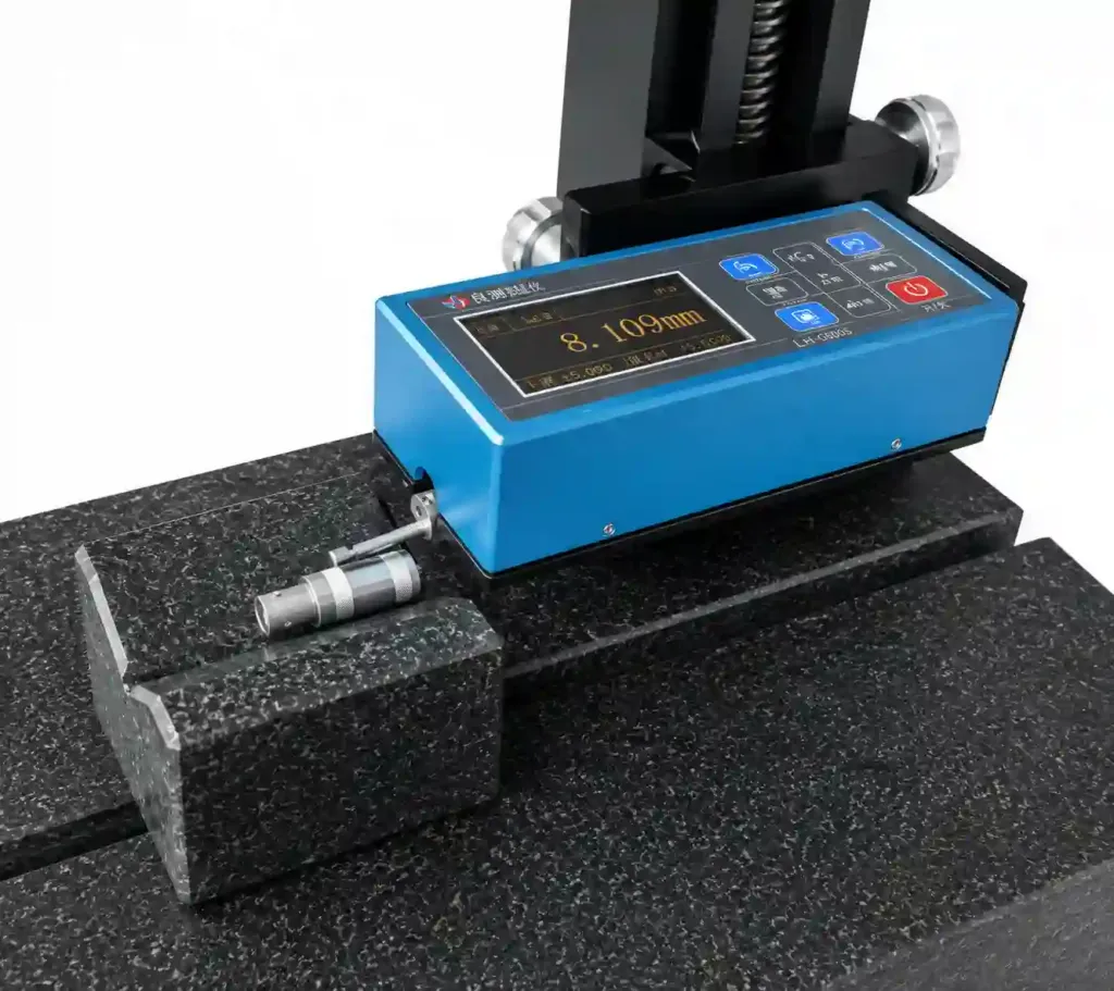
Correlate instruments without hiding measurement variability
Repeated readings can vary even after the nominal settings match. Trace placement, cleanliness, local damage, stylus condition, fixturing and instrument response can contribute. A correlation study should isolate these influences rather than averaging incompatible setups together.
Begin with a stable reference and a documented procedure, then repeat measurements at agreed locations. Where possible, compare the profile data as well as the final parameter. If the profiles differ substantially, investigate acquisition and positioning before debating the arithmetic used to calculate Ra.
Mitutoyo's surface-roughness quick guide documents the measurement chain, including stylus characteristics and profile filtering. It provides a useful framework for identifying what must match, while its referenced editions should be checked against the project’s specified standard.
Near an acceptance limit, use the agreed decision rule and measurement uncertainty approach. Do not round a marginal result in whichever direction favors acceptance. Also avoid a blanket conversion factor between instruments or between Ra and Rz. Surface geometry determines the relationship, so a correlation established on one texture may not transfer to a differently machined or finished surface. Record the scope of any demonstrated agreement.
Preserve the surface requirement in the drawing and report
The drawing should identify the functional surface, parameter, unit and applicable specification basis. Where defaults are unsuitable, communicate the required scale settings, direction or evaluation region using the selected standard’s conventions. A separate approved inspection instruction can carry detailed setup information without cluttering the part view.
Define the surface state and any permitted cleaning or preparation. Inspection must not polish away the feature being assessed. For interrupted geometry, resolve the method and acceptance basis before release, including whether results from multiple accessible regions are representative.
The report template should preserve actual settings rather than relying on operator memory. Include a trace-location reference, measured values and any deviations. The inspection requirements should also state how disagreements will be correlated, particularly when supplier and receiving instruments differ.
When a process changes, review whether the texture’s character or lay changes as well. The same Ra limit can conceal a different surface morphology, and the previously agreed measurement setup may need engineering review. A robust handover preserves the reason for the setup so that a later operator does not mistake a historical preset for an immutable property of the part.
FAQ
Does a 3.2 surface-finish note always mean Ra 3.2 micrometers?
Only when the drawing's symbol, unit convention and applicable specification establish that interpretation. A bare number is ambiguous outside its drawing context. Check the parameter, units and relevant notes rather than converting it from habit. If the drawing is incomplete, obtain clarification before machining or acceptance. This is particularly important when legacy drawings, inch-based records and newer measurement reports are exchanged between organizations using different default conventions.
Can a visual comparator replace the documented profilometer result?
A comparator can support process checks or an agreed visual assessment, but it does not automatically reproduce the defined numerical profile measurement. Surface lay, lighting and material appearance can affect the comparison. If it is proposed as an acceptance method, establish its scope and correlation for the actual texture. Keep that agreement distinct from a specified instrument-based requirement, especially where a marginal numerical limit or a functional sealing surface is involved.
Should inspection avoid every scratch to obtain representative roughness?
The treatment of local defects must follow the agreed requirement and evaluation procedure. Automatically steering around every visible mark can hide a functional problem; automatically treating every isolated defect as the underlying texture can answer a different question. Identify whether the drawing controls texture, defects or both. Record significant local damage separately where appropriate, and retain trace locations so that a disagreement can be investigated without selectively choosing favorable regions.
Conclusion
A roughness disagreement is often a disagreement about the measurement definition. Cutoff, filtering, evaluated length, direction and surface state determine what the reported parameter represents. Matching a parameter name and unit is necessary but insufficient.
Resolve access on short or interrupted features before inspection begins. When an alternative method is required, establish its relationship to the functional requirement and keep its limits visible. Correlation should compare both acquisition conditions and profile processing, with particular care near an acceptance boundary.
For a finish-sensitive component, send 6CProto the surface callout, functional land geometry and required measurement procedure. This allows machining, finishing and inspection access to be reviewed together, so that the delivered report describes the same surface information your receiving team intends to accept.
{“@context”: “https://schema.org”, “@type”: “FAQPage”, “mainEntity”: [{“@type”: “Question”, “name”: “Does a 3.2 surface-finish note always mean Ra 3.2 micrometers?”, “acceptedAnswer”: {“@type”: “Answer”, “text”: “Only when the drawing’s symbol, unit convention and applicable specification establish that interpretation. A bare number is ambiguous outside its drawing context. Check the parameter, units and relevant notes rather than converting it from habit. If the drawing is incomplete, obtain clarification before machining or acceptance. This is particularly important when legacy drawings, inch-based records and newer measurement reports are exchanged between organizations using different default conventions.”}}, {“@type”: “Question”, “name”: “Can a visual comparator replace the documented profilometer result?”, “acceptedAnswer”: {“@type”: “Answer”, “text”: “A comparator can support process checks or an agreed visual assessment, but it does not automatically reproduce the defined numerical profile measurement. Surface lay, lighting and material appearance can affect the comparison. If it is proposed as an acceptance method, establish its scope and correlation for the actual texture. Keep that agreement distinct from a specified instrument-based requirement, especially where a marginal numerical limit or a functional sealing surface is involved.”}}, {“@type”: “Question”, “name”: “Should inspection avoid every scratch to obtain representative roughness?”, “acceptedAnswer”: {“@type”: “Answer”, “text”: “The treatment of local defects must follow the agreed requirement and evaluation procedure. Automatically steering around every visible mark can hide a functional problem; automatically treating every isolated defect as the underlying texture can answer a different question. Identify whether the drawing controls texture, defects or both. Record significant local damage separately where appropriate, and retain trace locations so that a disagreement can be investigated without selectively choosing favorable regions.”}}]}