

An O-ring seal that leaks in testing looks like a material or a groove problem, and the fix often starts with the drawing: the gland was machined to a depth that over-compresses the O-ring, the width trapped it without room to swell, or the surface finish tore it during assembly. O-ring grooves are one of the most standard features in machined parts, and the standards make them easy to get right — the gland dimensions, the squeeze, the surface finish, and the corner radii are defined for the O-ring size and the application. The groove design is where the seal is made, and the drawing is where the seal is specified.
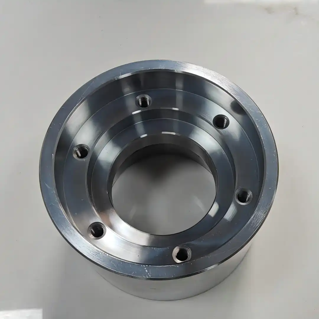
Gland types: static, dynamic, face, and radial
The gland design starts with the seal type. A static seal compresses the O-ring between two non-moving surfaces; a dynamic seal works with the O-ring moving against a surface, with different squeeze and lubrication requirements; a face seal compresses the O-ring between two faces; and a radial seal fits the O-ring in a groove on a bore or a shaft. Each gland type has its own dimensions and its own failure modes: a static face seal is the simplest, while a dynamic rod seal needs the squeeze and the finish tuned for the movement. The gland type should be identified first, because the groove dimensions and the tolerances follow it.
The seal standard — such as the O-ring gland dimension references — provides the tables for each gland type, and the drawing should use the table that matches the application.
Squeeze and compression: how groove depth controls sealing
Squeeze is the percentage that the O-ring is compressed in the gland, and it is set by the groove depth relative to the O-ring cross-section. Too little squeeze and the seal leaks at low pressure; too much squeeze and the O-ring over-compresses, increases the friction, and fails early. The recommended squeeze range depends on the seal type — static seals typically run a higher squeeze than dynamic seals — and the gland depth is machined to deliver the target squeeze at the tolerance. The squeeze also changes with the temperature and the material swell, and the design should account for the O-ring’s behavior in service. The groove depth is the dimension that controls the seal, and it is the dimension that the machining must hold.
The squeeze should be verified with the actual O-ring and the assembly, because the O-ring’s tolerance and the surface stack change the result.
Dimensions: gland depth, width, and corner radii
The gland dimensions follow the O-ring size and the gland type. The depth sets the squeeze; the width provides the space for the O-ring to swell and to move in dynamic service; and the corner radii at the groove edges prevent the O-ring from being cut or pinched during assembly. The gland width should not be so tight that the O-ring cannot swell, nor so loose that it rolls or extrudes; the standard tables give the width for the O-ring cross-section. The corner radii are small but critical: a sharp corner can nick the O-ring, while too large a radius reduces the retention. The groove dimensions are machined from the standard, and the drawing should carry the depth, the width, and the radii with the O-ring size.
The groove diameter in a radial gland is also critical, because it sets the O-ring’s stretch and the seal’s compression on the mating surface.
Surface finish requirements in the seal area
The surface that the O-ring seals against must carry the right finish. A surface that is too rough tears the O-ring and leaks; one that is too smooth can fail to hold the lubricant film in dynamic service. The seal surface finish is specified in the gland standard, and the machining should produce the required range on the functional surface. The finish direction also matters in dynamic seals, where the lay should follow the motion to avoid scoring the O-ring. The drawing should carry the finish requirement on the sealing surface, and the inspection should verify it with the roughness measurement. The O-ring seal is made at the surface, and the finish is part of the seal specification.
The finish should be measured on the actual sealing surface, in the direction that the O-ring moves or compresses, because the measurement location and direction set the result.
Drawing and inspection notes for O-ring grooves
The groove drawing should carry the complete set: the O-ring size and material, the gland type, the groove depth, width, and diameters, the corner radii, the surface finish on the seal face, and the assembly note. The critical dimensions are marked for inspection, and the inspection verifies the groove against the O-ring and the gland standard. The drawing should also note the surface that the O-ring seals against when it is a separate part, so the two surfaces are machined to the same requirement. A groove that is drawn completely is a feature the shop can machine and inspect; one that is left partial is a seal that fails at the first test.
Validating the seal on the first assembly
The O-ring seal should be validated on the first assembly, where the groove, the O-ring, and the mating surface meet. The assembly test presses the seal to the service pressure, checks for the leaks at the operating and the test conditions, and verifies the O-ring is not damaged during the assembly or the disassembly. The validation results confirm the gland dimensions and the finish, and they catch the issues that the drawing cannot: an O-ring that rolls in an oversized groove, a surface that tears the seal, or a compression that is too high for the material. The first-article seal test is the proof that the groove design works, and the adjustments are made while the part is still being qualified. An O-ring groove that is validated on the first assembly is a seal the production run can trust.
The validation should also cover the service condition — the temperature, the pressure cycles, and the fluid compatibility — because the O-ring’s behavior changes with the environment. The seal test at the service condition confirms the material and the gland for the real duty, and the results are recorded with the drawing. The production inspection checks the groove dimensions and the finish at the interval that catches the drift, and the O-ring source is controlled so the seal is consistent. When the groove is validated and the O-ring is controlled, the seal is an engineered feature — and the assembly that holds pressure in the test is the assembly that holds pressure in service.
The O-ring groove design should also be reviewed with the assembly and the maintenance, because the seal’s life depends on how the parts are joined and serviced. The assembly that presses the O-ring past a sharp edge or a thread can nick it before the seal seats; the design should include the lead-in chamfers and the assembly sequence that protect the O-ring. The maintenance that replaces the O-ring should be able to remove the old seal and install the new one without damaging the groove, and the drawing should note the service access. The O-ring material and its shelf life are part of the maintenance plan, and the spares should be specified to the same grade as the original. When the groove design is reviewed with the assembly and the maintenance, the seal is designed for its whole life — the first assembly, the service cycles, and the replacement — rather than for the static test alone. The seal that survives its service is the seal whose groove, assembly, and maintenance were designed together.
Keep the groove specification and the seal test with the part, so the gland dimensions and the O-ring source are consistent across the orders. The record is the reference for the inspection and the seal review when the service changes.
Confirm the O-ring source and the groove dimensions with the supplier, and verify the first assembly at the service pressure. The confirmed source and the verified assembly are what make the seal reproducible, and the record is the reference for the production run.
Keep the gland and the finish on the drawing, verify the seal at the service condition, and the O-ring joint becomes a controlled feature rather than a test failure.
Verify the groove and the seal at the service pressure on the first assembly, and keep the O-ring source and the dimensions with the drawing so the seal is reproducible.
Verify the groove dimensions and the seal at the service condition on the first article, and record the O-ring source and the test with the drawing so the seal is reproducible and auditable.
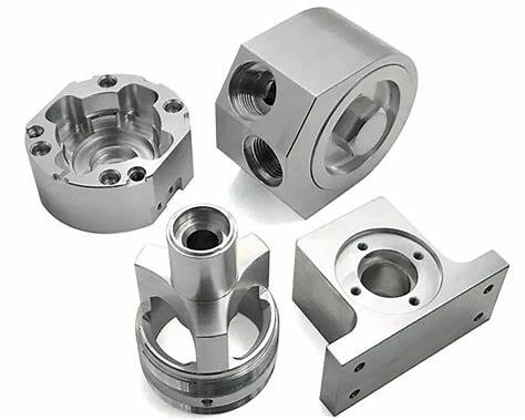
If you are designing an O-ring groove for a machined part and want the gland dimensions, the finish, and the inspection plan reviewed, the 6CProto CNC team can work from your O-ring and your service pressure to the groove specification.