

Updated
Separate the texture produced by machining from a later treatment such as anodizing or plating. One controls aspects of geometry; the other changes the surface system and may also change dimensions or appearance. This guide shows how to make both requirements measurable without over-specifying the entire part.
Specify CNC surface finish around the working surface
CNC surface finish combines measurable surface texture with any required post-processing condition. Ra describes average profile roughness; it does not fully describe scratches, lay, waviness or coating quality. Define the functional surface first, then select the texture parameters, treatment and inspection conditions needed to accept that feature.
A noncontact exterior may tolerate tool marks that are unacceptable on a sliding interface. A sealing land may need control of directional scratches as well as roughness. A cosmetic face may require a reference sample and viewing conditions even when its Ra result is satisfactory.
Write local requirements where function demands them and use a practical general requirement elsewhere. This prevents every hidden pocket from inheriting an expensive finish chosen for one bearing surface. The CNC machining route should be reviewed against the features that need special passes or secondary work, not against a universal claim that all machined parts naturally achieve one Ra value.
Read Ra, Rz and waviness without treating them as equivalents
Ra is the arithmetic mean of the absolute roughness-profile deviations from the mean line over the relevant length. Because it averages the profile, it can hide an isolated peak or deep valley. Two surfaces with the same Ra can have different distributions of height and different performance.
Rz is a height parameter whose definition and evaluation must be tied to the applicable standard. Do not label every Rz result as the average of five peaks and five valleys: that description corresponds to a historical ten-point convention, not a universal definition of Rz. Old instruments and drawings can use different parameter implementations.
ISO 21920-2:2021 specifies profile terms and parameters. Mitutoyo’s surface-roughness guide also illustrates why parameter choice and measurement conditions matter, though its legacy standard references should not silently replace a current drawing’s requirements. Distinguish roughness from longer-scale waviness and form: reducing fine tool marks does not necessarily correct a bowed sealing face or chatter pattern.
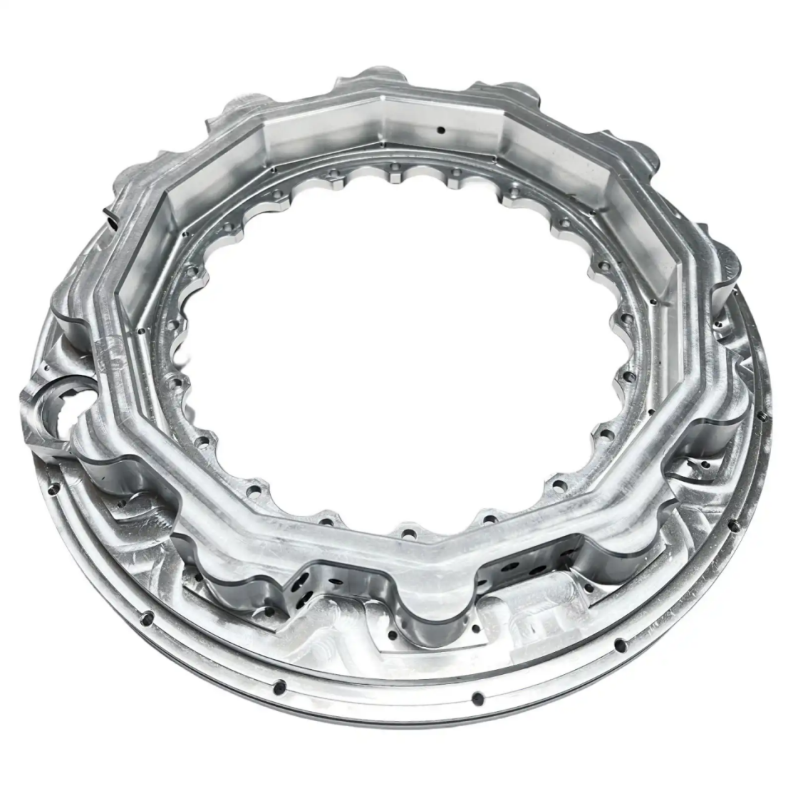
Ra values and unit conversions for drawing review
The values below are specification examples and arithmetic conversions, not guaranteed process capabilities or recommended limits for every application. Smaller Ra describes a smoother average profile under the same evaluation conditions. It does not establish which value a seal, bearing or cosmetic face needs.
Keep the parameter and unit together. A bare 3.2 on a drawing is insufficient outside its defined surface-texture convention; 3.2 micrometers and 3.2 microinches are very different requirements.
| Ra in µm | Approximate Ra in µin | Drawing-review question |
|---|---|---|
| 0.4 | 15.7 | Does the feature need this level and is inspection access available? |
| 0.8 | 31.5 | Is the final condition measured before or after treatment? |
| 1.6 | 63.0 | Are lay and local defects also relevant to function? |
| 3.2 | 126.0 | Is this a local requirement or the intended general limit? |
| 6.3 | 248.0 | Are tool marks acceptable on this particular surface? |
The conversion is µin = µm / 0.0254. For example, 3.2 / 0.0254 = 125.984 µin, rounded here to 126.0. Do not convert Ra into Rz with a fixed multiplier. Different surface profiles can give the same Ra and different height parameters, so a parameter conversion would require additional information about the surface.
Control measurement settings before comparing results
A roughness number is meaningful only with the evaluation method that produced it. Establish the applicable standard, filtering or nesting-index settings, evaluation length, trace direction and measurement location. Record approved exceptions when a short land or inaccessible recess cannot accommodate the normal evaluation.
A trace along the lay can differ from one across it. A stylus also interacts with narrow valleys, surface slope and local geometry, so the instrument must be suitable for the feature. A short trace chosen merely because it fits on the part should not be presented as equivalent to a longer specified evaluation.
ISO 21920-3:2021 addresses specification operators for profile texture. Avoid importing a familiar legacy cutoff into a drawing that uses a different framework. For disputed results, exchange the actual profiles and settings before changing the limit. This can distinguish a true process difference from different filtering, trace direction or measurement coverage.
Improve the cutting process before adding a finishing operation
When tool marks or chatter drive the problem, investigate the cutting process before assuming a coating or manual polish will solve it. Review tool condition, edge geometry, feed, workholding stiffness, tool reach and chip evacuation. The most relevant variable depends on the shape and material being cut.
A larger nose radius can change the generated profile but also increase sensitivity to force and vibration in a weak setup. A lighter finishing cut can help in one situation and create rubbing in another. Sandvik Coromant’s turning-geometry guidance explains why an insert geometry must suit the finishing cut rather than merely be labeled suitable for the material.
Keep a reference part and preserve the failed profile when adjusting the process. If a broad waviness pattern remains while fine marks improve, the root issue is still unresolved. For a difficult accessible land, an additional controlled operation may be justified; for an inaccessible internal surface, changing geometry or inspection access may be more effective than writing a tighter number on the drawing.
Choose finishing options by their effects on fit and surface
A treatment name does not specify a roughness result. Polishing removes material; blasting changes texture; anodizing, plating and paint introduce treatment-specific dimensional and surface effects. The selection should preserve the feature’s fit while solving the actual appearance, wear or environmental requirement.
The following comparison identifies the main questions for a DFM and finishing review. Process feasibility and final values still depend on material, geometry and the complete treatment specification.
| Option | Main purpose | Dimensional concern | Acceptance detail |
|---|---|---|---|
| Controlled as-machined finish | Functional geometry with specified texture | Tool access, burrs and cutting-induced form error | Local parameters, lay and defects where needed |
| Polishing or lapping | Reduce selected surface irregularities | Material removal, edge rounding and local form change | Final size, geometry and texture |
| Bead blasting | Create a more uniform matte texture | Exposure of sensitive features and altered surface texture | Masking, media and appearance standard |
| Anodizing | Specified oxide treatment on suitable aluminum | Treatment effects on dimensions and masked transitions | Treatment, sealing, coverage and final fit |
| Plating | Specified metallic surface system | Layer buildup and nonuniform coverage | Layer specification, thickness and final acceptance |
| Paint or powder coating | Color and barrier system | Buildup at mating features and edge coverage | Pretreatment, cure, film and cosmetic criteria |
Review these decisions through surface finishing. Do not promise that blasting removes every machining mark, that polishing preserves every sharp edge or that an attractive coating establishes an Ra limit. Specify the final result where it matters.
Separate sealing texture, bearing geometry and cosmetic acceptance
For a sealing face, consider the seal manufacturer’s requirements, pressure, relative motion and the direction of possible leakage paths. A single scratch crossing the seal contact can matter even when the average trace passes. Define defect limits or another relevant parameter when Ra alone cannot control that failure.
For sliding and bearing interfaces, review lubrication, contact and wear along with texture. Smoother is not automatically better: the surface system must suit the contact regime. Keep roundness, straightness and fit separate because those are geometric requirements with their own inspection methods.
For appearance, specify visible zones, lighting, viewing distance and a reference sample when required. A profilometer does not measure color consistency or every visible tool mark. ASME B46.1’s surface-texture scope includes roughness, waviness and lay; these terms help separate measurable texture from broader cosmetic requirements. Do not use the same acceptance sentence for every type of surface.
Put the final-condition requirement on the drawing
A complete local finish instruction identifies the surface, parameter, limit and governing standard. State whether it applies after all required treatments. Then identify masking and dimensional acceptance on features whose size or fit could change during finishing.
ISO 21920-1:2021 addresses texture indication in technical product documentation. A useful engineering-note example is: sealing land S1, Ra maximum 0.8 µm in the specified final condition, evaluated to the stated drawing standard and approved measurement plan. This illustrates the information to resolve; it is not a seal design recommendation or a complete graphical-symbol substitute.
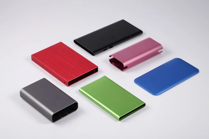
For an anodized aluminum component, confirm the treatment route and masked boundaries before manufacture. If an area remains uncoated, decide how its environmental requirement is met. Use the tolerance review to coordinate final size and geometry. A roughness note should not leave the supplier guessing whether an after-treatment correction is permitted.
Inspect the surfaces that determine acceptance
Plan trace access and representative locations while the drawing is still being reviewed. If the required surface is inaccessible to the selected instrument, agree on an appropriate alternative before production. A neighboring flat surface is not automatically representative of a deep bore or a curved sealing land.
Connect the reported value to the actual feature and final treatment condition. Preserve the profile for critical or disputed results and record settings needed to reproduce the evaluation. For a repeat batch, identify which tool, operation or finishing change could affect the controlled surface and review those changes in the inspection plan.
The right finish specification reduces unnecessary work while protecting the surfaces that matter. Require a tighter texture where it serves a defined function, add form or defect controls when averaging would hide the failure, and use appearance standards for visible zones. A lower Ra on every face is an expensive substitute for this feature-level decision.
Upload the drawing through 6CProto’s quote flow with critical surface zones, roughness parameters, final treatments and inspection requirements for a focused DFM review.
FAQ
Can a roughness comparator replace a profilometer?
A comparator can help screen a process or communicate a texture expectation, but it should not silently replace the measurement method required for acceptance. Its suitability depends on the surface type, limit and agreed procedure. For a critical numerical requirement, confirm whether comparator inspection is permitted and what evidence is recorded. A tactile or visual match alone may miss profile features that the specified parameter is intended to evaluate.
Can an optical instrument and a stylus report the same parameter?
They can report related texture quantities when the extraction and evaluation are appropriate, but their interaction with the surface is different. Reflectivity, steep slopes, narrow valleys and data filtering can affect correlation. Qualify the alternative method on representative surfaces and document the settings before using it for acceptance. A three-dimensional areal result such as Sa should not be relabeled as the profile parameter Ra.
How should protective packaging be chosen for finished surfaces?
Protect the features against scratches, contact marks and residue that could affect their acceptance or function. Avoid adhesive or wrapping contact on sensitive surfaces unless the cleaning and residue requirements permit it. Separate parts so they do not rub together during transit, and identify the protected surfaces in the packing instruction. Packaging should preserve the inspected final condition without hiding damage that must be checked on receipt.