

Explore Surface Preparation, Plating & Inspection
A finishing drawing can call for protection over most of a part while requiring selected bores and contact areas to remain in a different condition. If those zones are described only as mask as required, the processor must infer which function matters and where the transition belongs. That ambiguity can survive a visually attractive finish and appear only during assembly.
Aerospace surface finish masking is therefore a drawing and process-interface task. Define the surface state required at each functional zone, identify the boundary and agree how the final condition will be verified. Masking is one manufacturing method for achieving that result, not the acceptance requirement by itself.
The applicable customer and program documents determine the approved process, processor and evidence. The references below explain particular interface considerations; they do not replace those requirements or establish a general processing recipe.
The surface finishing service supplies the broader manufacturing context. This guide concentrates on communicating selective-treatment requirements for custom parts. Keep fit, adhesive bonding and electrical bonding distinct, because the surface condition suitable for one can be unsuitable for another.
Identify masked functional zones
Define the required surface state for each zone.
Identify bores, adhesive bond areas, electrical contacts and reference faces individually, then state which treatment is required or prohibited and why that distinction matters to the final interface.
A bore may need controlled final size, while a conductive contact may need a specified electrical performance. An adhesive bond area may instead require a particular preparation and contamination control. Calling all three bare metal can conceal requirements that differ significantly.
NASA’s aluminum-anodizing process specification discusses the need for electrical rack contact and identifying important contact locations on the drawing. Its application is specific; it illustrates why rack marks and prohibited-contact surfaces should be coordinated rather than left to inference.
Map the zones on the model or drawing with stable identifiers. Include hidden faces and internal openings that are difficult to see in the main view. State whether the restriction concerns the whole bore, a land, a thread or only a defined contact patch. The processor can then propose masking and racking without silently choosing the product’s functional boundaries.
Mask boundary and transition requirements
Locate the boundary from a measurable feature or datum. A shaded image can communicate intent but may not establish where treatment may stop or begin. Provide the permitted transition region and any limits on overlap or encroachment where the interface needs them.
Distinguish the coating boundary from the edge of the masking material. The manufacturing method can have a transition that needs evaluation after removal. Specify the finished requirement rather than assuming a perfectly sharp division at the tape edge.
The ASME drawing framework supports clear references and geometric requirements. It does not supply a generic masking tolerance. A functional land and a cosmetic border can justify different boundary controls; assign them deliberately instead of applying an unsupported precision value everywhere.
Consider accessibility for inspection. A boundary deep inside a bore may be difficult to measure or photograph after finishing. Agree the verification route before production, including whether a sectioned development specimen or another method is needed. If the boundary cannot be demonstrated by the proposed method, resolve that gap before accepting a mask layout solely because it appears clear in CAD.
Process compatibility and removal
Select masking for the actual treatment sequence. Bath chemistry, temperature, duration, cleaning and downstream operations can affect adhesion, leakage and removal. A material suitable for one finishing process should not be assumed suitable for every process sharing a similar name.
3M’s anodization-masking guidance distinguishes bath compatibility and removal behavior among masking products. Use the selected product’s technical information with the processor’s approved route; the guide does not approve a complete aerospace treatment system.
Review removal as part of the operation. Residue, trapped fragments or damage from extraction can defeat the purpose of protecting a bore or contact. Identify any cleaning and handling controls required after removal and before the surface is used for assembly.
Keep adhesive bonding separate from electrical bonding. A surface reserved for adhesive bonding may require controlled preparation rather than simply remaining untreated. Identify the applicable bonding-process document and contamination restrictions. If the masking route introduces a prohibited residue or requires an unapproved cleanup, revise the route instead of declaring the interface protected because no visible coating is present.
Verify dimensions and continuity after finishing
Inspect the delivered condition after the relevant treatment and masking-removal stages. A bore measured before finishing provides useful process information, but it does not establish its final fit. Likewise, a visually clear contact patch does not prove the electrical performance of an assembled connection.
NASA’s electrical-bonding design handbook addresses bonding interfaces and corrosion considerations. Preserve its scope when using it as context: electrical bonding concerns an intentional conductive connection, not an adhesive joint or a general bare-surface appearance requirement.
Define the final measurements separately. The bore needs its specified geometry; the conductive interface needs the applicable continuity or resistance evidence; the adhesive area needs the specified preparation and acceptance. A masking inspection can confirm boundaries without answering all these functional questions.
For precision-machined interfaces, identify whether dimensions apply before or after finishing. If a secondary machining operation is proposed to restore a fit, review whether it changes protection or exposes a surface that needs another controlled treatment. Do not solve a dimensional issue by silently changing the required surface state.
Masked-zone units and final acceptance conditions
Use a zone schedule to connect the treatment drawing with inspection. Each row should state what the final surface must be and which condition is being measured. A single general finish note cannot reliably express several different functional interfaces.
The table below is an information structure, not a processing specification. Supply the actual limits and methods from the governing product and program documents.
| Zone | Requirement to define | Final evidence |
|---|---|---|
| Fit bore | Final dimensions and allowed treatment state | Geometry after the specified sequence |
| Adhesive area | Preparation and contamination restrictions | Required process and acceptance record |
| Electrical contact | Surface condition and conductive function | Applicable connection verification |
| Mask transition | Permitted boundary region | Location and coverage inspection |
Record units explicitly and avoid a default interpretation that all dimensions precede treatment. Identify any reference specimen used for a transition or appearance decision. That specimen should support the controlled requirement rather than replace it with an unmeasurable visual preference.
A bore and contact-land masking review
Consider a hypothetical bracket with a fitted bore and an adjacent electrical contact land. The bore requirement controls final fit, while the land requirement controls the intended connection surface. They may share a nearby mask boundary without sharing the same acceptance test.
Show the bore extent in section and locate the land from the product datums. Mark the permitted transition region so a coating edge cannot migrate into the required contact area. Also identify rack-contact restrictions where the finishing route needs them.
Ask the processor to propose access, masking and removal methods. Review whether a plug can be withdrawn without scratching a critical bore and whether removing the land mask can transfer residue onto another functional surface. These are method questions to resolve before the first production batch.
After the trial, inspect the bore, land and boundary independently. Preserve images and measurements linked to the zone identifiers. A successful bore result does not approve the contact function, and a satisfactory electrical result does not establish bore size. The value of the trial is the connection between a repeatable process detail and each required final condition.
Boundary measurement and verification limitations
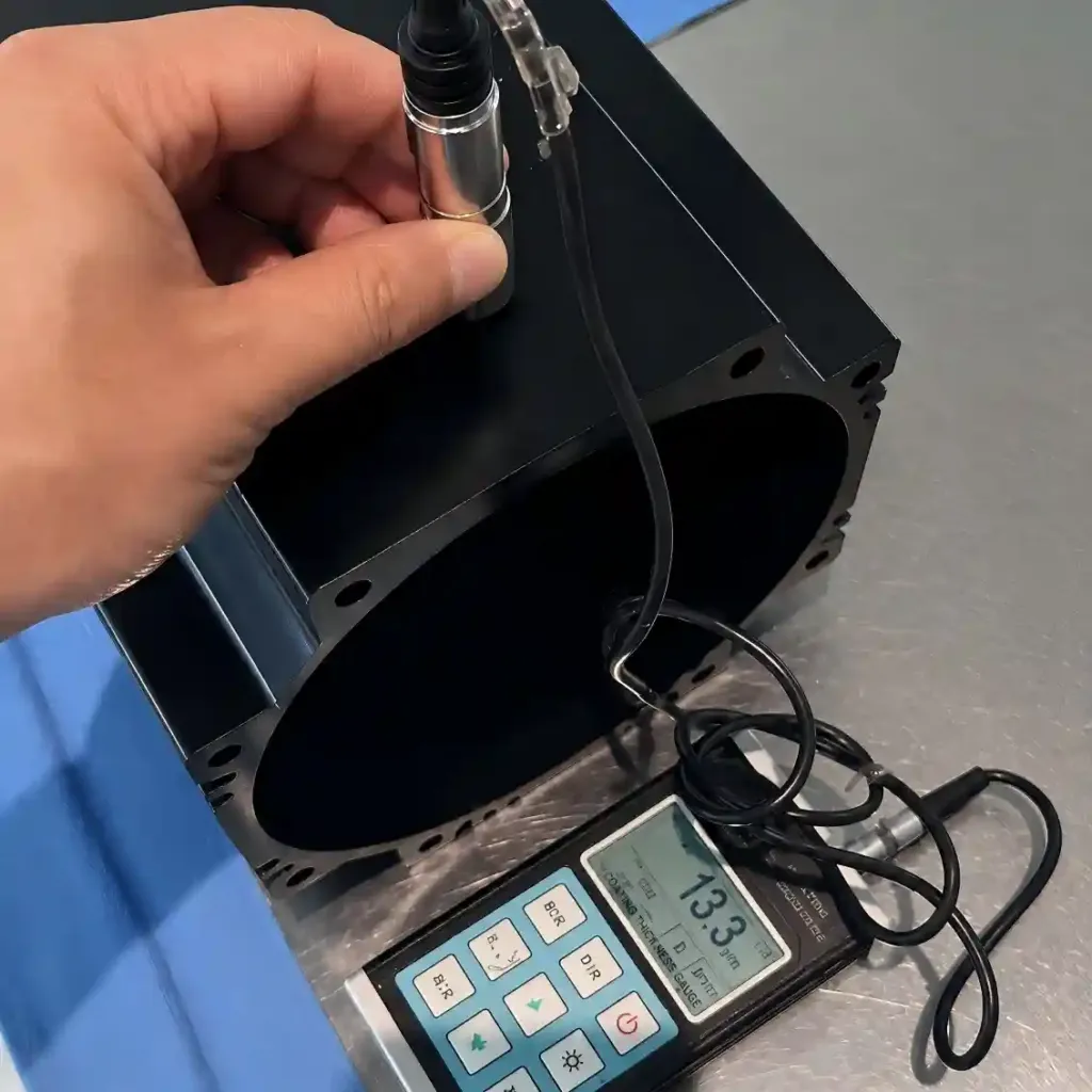
Choose a method that can distinguish the permitted boundary and surface condition. Optical appearance, coating-thickness measurement and dimensional inspection answer different questions. A color transition can be useful evidence but should not automatically become the accepted treatment boundary if the process can produce a less visible transition.
Record access limitations on internal zones. A probe or camera may observe only part of a bore, and a witness specimen may experience a different local condition from the part. State what the method demonstrates and where supplementary evidence is needed.
NIST’s uncertainty-analysis guidance connects measurement quality with fitness for a decision. Apply that reasoning when a narrow boundary region or small dimensional change controls release. Instrument resolution alone does not establish that the actual zone can be inspected adequately.
Use repeated positioning where it affects the result, and retain the measurement references. Do not make a more precise claim than the evidence supports. If the boundary cannot be resolved or the specified interface cannot be verified, revise the measurement plan or processing detail before treating an attractive finish as acceptance.
Mask drawing and processor handoff requirements
Supply the material, finish specification, zone schedule and final dimensional requirements together. Identify the applicable revisions and any customer approval requirements for the process or processor. Keep manufacturing proposals separate from design authority over the final surface condition.
Request a review of ambiguous boundaries, restricted rack locations, masking access and removal. Define how deviations will be submitted and who can approve them. A processor’s practical suggestion can improve the route, but it should not silently redefine a bond area or fit bore.
State the evidence package needed for release: zone-based inspection, specified process records, relevant final dimensions and any required functional verification. Where a development specimen is consumed, identify its relationship to the delivered parts and the limit of the inference.
The standards and tolerances reference provides discussion context. The governing drawing and program documents control the actual requirement. Retain the approved masking detail and any trial disposition with the revision so repeat orders preserve the intended interfaces rather than merely reproduce the overall finish appearance.
FAQ
Can a final bore be machined after coating instead of masked?
That may be a viable proposed route only when the resulting geometry and exposed surface condition comply with the governing requirements. Removing treatment can change protection and the relationship to nearby interfaces. Identify the secondary operation explicitly and obtain the required approval before using it as a substitute. Verify the final bore and any affected boundary after the complete sequence rather than relying on a pre-treatment dimension.
Does an uncoated patch prove an electrical bond will pass?
No. The assembled connection depends on the specified surfaces, contact arrangement and applicable verification method. Visible absence of coating is one observation, not a complete electrical performance result. Keep the required surface condition and the connection test distinct in the drawing and inspection plan. Also retain corrosion protection and maintenance requirements around the interface where the governing documents call for them.
Can a processor move a rack-contact point without revising the mask drawing?
It depends on the controlled requirements and approval route. If the location is restricted or affects a functional interface, the change needs review under those documents. Even when an alternate location is allowed, record it where it influences inspection or repeatability. Ask the processor to identify contact proposals before treatment so a necessary process feature does not become an unexpected mark on a protected functional surface.
Conclusion
A useful masking specification describes final interfaces, measurable boundaries and the evidence needed after processing. Separate fitted geometry, adhesive preparation and electrical contact requirements, then review the masking and racking methods against each one. An overall finish designation cannot make those local decisions by itself.
Keep the approved process and customer requirements attached to the drawing. Confirm access and removal during development and inspect the delivered condition after the complete sequence. Where the proposed method cannot demonstrate an internal boundary or functional interface, resolve that limitation before release.
For a manufacturing review, upload the part CAD, finish specification and identified masking zones. Include final dimensions and the applicable approval requirements so 6CProto’s DFM review can assess the drawing and process interfaces against a concrete product definition.
{“@context”: “https://schema.org”, “@type”: “FAQPage”, “mainEntity”: [{“@type”: “Question”, “name”: “Can a final bore be machined after coating instead of masked?”, “acceptedAnswer”: {“@type”: “Answer”, “text”: “That may be a viable proposed route only when the resulting geometry and exposed surface condition comply with the governing requirements. Removing treatment can change protection and the relationship to nearby interfaces. Identify the secondary operation explicitly and obtain the required approval before using it as a substitute. Verify the final bore and any affected boundary after the complete sequence rather than relying on a pre-treatment dimension.”}}, {“@type”: “Question”, “name”: “Does an uncoated patch prove an electrical bond will pass?”, “acceptedAnswer”: {“@type”: “Answer”, “text”: “No. The assembled connection depends on the specified surfaces, contact arrangement and applicable verification method. Visible absence of coating is one observation, not a complete electrical performance result. Keep the required surface condition and the connection test distinct in the drawing and inspection plan. Also retain corrosion protection and maintenance requirements around the interface where the governing documents call for them.”}}, {“@type”: “Question”, “name”: “Can a processor move a rack-contact point without revising the mask drawing?”, “acceptedAnswer”: {“@type”: “Answer”, “text”: “It depends on the controlled requirements and approval route. If the location is restricted or affects a functional interface, the change needs review under those documents. Even when an alternate location is allowed, record it where it influences inspection or repeatability. Ask the processor to identify contact proposals before treatment so a necessary process feature does not become an unexpected mark on a protected functional surface.”}}]}