

Explore Surface Preparation, Plating & Inspection
A polished component can have a lower roughness value and still fail because the edge of a locating shoulder has receded. The finish looks improved, while the geometry that establishes contact has changed. Acceptance needs to protect that geometry independently of the surface-texture requirement.
Precision surface finish and edge rounding should therefore be specified as related but separate outcomes. Burr removal, an intentional edge break, a chamfer and a rounded transition are not interchangeable instructions. The required condition depends on how the edge locates, seals, guides or contacts another component.
This guide focuses on controlling material removal at functional boundaries. It does not rank polishing methods by shine or prescribe a universal maximum radius. The process needs to remove the unwanted condition while retaining the geometry the assembly actually uses.
Include the final edge requirements in the surface-finishing review. A broad instruction to polish all surfaces can otherwise authorize work on a knife edge, shoulder or sealing land that needed protection. Mark those distinctions before selecting media, masking or a localized finishing route. Keep the intended datum contacts visible in the review, because a narrow surface near the edge can control seating even when its cosmetic importance is low.
What must precision surface finish and edge rounding control?
Specify burrs, texture and edge geometry separately.
A lower roughness value does not establish the retained shoulder position or edge radius, so define each functional boundary alongside the surface-texture condition before approving a finishing process.
Start by identifying the unwanted material. A burr protrudes from the intended surface; an edge break removes material from the nominal sharp intersection. Removing a burr can be necessary without permitting an unrestricted retreat of the parent edge.
Rösler's edge-rounding guidance distinguishes deburring from the production of a defined rounded edge. That process distinction supports separate drawing requirements. A note requesting burr-free parts should not silently become permission for any radius a batch process produces.
Consider the mating geometry. A rounded shoulder can shorten a locating face or contact a mating corner before the intended flat seats. Define the allowable transition envelope where a simple radius does not describe the actual function. Keep intentionally sharp or controlled edges explicitly identified, with a manufacturing and inspection method suited to them.
Finishing access and media contact
A batch finishing process does not contact every region in the same way. Exposed corners, internal pockets, narrow slots and shielded faces can experience different contact and material removal. Review the actual component geometry and loading arrangement rather than assuming a uniform finishing effect.
Rösler's ceramic-media guidance relates media shape, size and formulation to the workpiece and required result. The choice must also consider access and separation from holes or recesses. Media that enters a feature but cannot be removed creates another acceptance problem.
Inspect neighboring features that need little or no edge change. Local masking, fixtures, process sequencing or another finishing route may be appropriate, but each needs a representative trial. A protected edge can also create a transition or leave an untreated region that needs inspection.
Record the process inputs that affect contact: media identity and condition, part loading, orientation where controlled, and the approved processing sequence. Avoid specifying a generic time alone as proof of the final edge. The same nominal time can produce a different result after media wear, loading or geometry changes.
Protect sealing and locating edges
Map the edges whose position or shape affects function. These may include seal-land boundaries, datum shoulders, port intersections, metering edges and small bearing faces. A visually smooth transition can be unacceptable where the design needs a specific contact width or flow geometry.
Define what must remain after finishing. A minimum flat width, a maximum material-removal envelope or a controlled transition profile may express the requirement more directly than a general cosmetic radius. Choose dimensions that relate to the assembly function and can be verified.
Keep final-state requirements connected to the precision-machined geometry. If machining leaves an allowance for finishing, identify which faces and edges carry that allowance. Do not distribute an assumed stock-removal value across every surface without a validated process basis.
Check the mating component and assembly sequence. An edge that guides a seal into place may need a controlled lead-in, while an adjacent edge defines the final contact. Label them separately. Protecting one boundary by moving material into another contact region can simply relocate the functional failure.
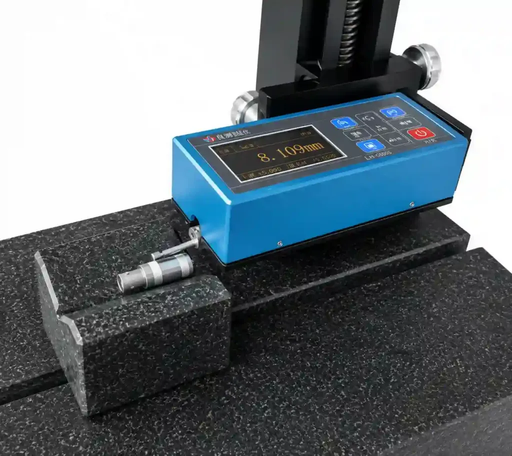
Measure the final edge profile
Select a measurement method that can observe the transition relative to the adjoining functional faces. Measuring roughness on the center of a flat does not reveal how far the edge has rounded back. The profile needs its own reference construction and acceptance region.
Mitutoyo's profile-projector information describes optical dimensional measurement. For a particular edge, verify orientation, focus, contrast and access before using an optical silhouette as the accepted profile. Reflective surfaces and three-dimensional transitions can complicate the apparent boundary.
Define whether the measured quantity is a fitted radius, chamfer width, flat width or profile deviation from an envelope. A fitted circle can conceal an irregular transition if only a small arc is sampled. Preserve the actual trace where its shape matters.
Record representative positions along the edge. A single accessible section may miss local over-rounding near a corner or a process contact point. Compare pre-finish and post-finish locations when investigating material loss, using compatible datums so setup changes are not mistaken for finishing removal.
An acceptance map for texture and retained geometry
The drawing and inspection plan should give each requirement a distinct role. Texture applies to a defined surface region; edge geometry applies to its boundary; dimensional location applies to the faces that establish assembly. Passing the texture requirement cannot override the other two.
The following table provides a comparison structure. Enter project-specific values after the function and measurement method have been agreed.
| Requirement | Reported quantity | What it does not prove |
|---|---|---|
| Surface texture | Specified parameter and measurement settings | Retained edge location |
| Edge transition | Radius, width or profile envelope | Entire flat’s roughness |
| Locating face | Position, orientation and remaining width | Absence of loose burrs |
| Burr condition | Defined residual envelope | Permissible parent-material removal |
KEYENCE's Ra explanation describes an average profile-height quantity. Its meaning does not extend to the entire macrogeometry of an edge. Keep parameter selection and sampling conditions explicit rather than treating a single low Ra number as evidence of every desired finishing outcome.
Interpreting a smooth part that no longer seats
Consider a hypothetical locating ring that passes its surface-texture check but rocks against a mating shoulder after polishing. Preserve the finished part and examine the actual contact. A smoother surface is compatible with a geometric problem and does not identify which feature moved.
Compare the retained flat, transition region and mating corner against the drawing. Look for edge retreat, uneven removal, a residual burr or a transition that contacts before the intended face. Measure the geometry from the agreed references rather than comparing photographs alone.
If a pre-finish measurement exists, align it using compatible datums before calculating removal. If it does not, record the uncertainty in attributing the change to finishing rather than machining. Compare identified trial parts from the same route where useful.
Run the corrective trial with both geometry and texture acceptance active. A shorter or less aggressive process may preserve the shoulder while leaving another surface below its texture requirement. The approved route must satisfy both, or allocate the surfaces to different controlled operations.
Avoiding measurement and specimen-preparation artifacts
An inspection method can alter or misrepresent the edge being assessed. A compliant support can tilt a small part; a contact probe can bridge a narrow transition; an optical system can interpret an uncertain bright boundary as the edge. Check these effects before reporting a small geometry change.
If a sectioned specimen is used, preserve the edge during preparation. Struers' materialographic preparation guidance discusses edge rounding as a preparation artifact. This evidence concerns specimen preparation, not the production finishing process, but it explains why a polished section can distort the very transition being investigated.
Document mounting and preparation details alongside the section image. A rounded specimen edge should not automatically be attributed to the supplier’s finishing operation. Compare another suitable method when the interpretation materially affects disposition.
Evaluate repeatability and uncertainty for the actual profile quantity. More repeated traces do not correct an unsuitable datum or an edge altered by preparation. When the method cannot distinguish the acceptance boundary, improve the measurement route before sorting production parts or changing the process.
Drawing and process controls for the finished edge
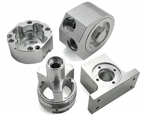
Mark functional edges individually and specify the accepted final condition. Keep unrestricted cosmetic transitions separate from sealing, locating and flow-control boundaries. A general edge-break note should identify its exceptions so operators can recognize them without interpreting assembly intent.
Reference a controlled process plan when media, masking or local finishing details are essential to repeatability. Preserve the approved trial’s part revision, material condition and inspection results. A process setting is useful only when its relationship to the finished requirement has been demonstrated.
Use the standards and tolerances reference to frame the specification discussion, while retaining the actual edge and texture callouts on the drawing. Avoid approving a family of parts solely from a coupon that lacks the difficult corners or protected features.
Define how rework is authorized. Additional polishing removes additional material, so a cosmetic correction needs another check of the remaining functional geometry. Once a critical edge has receded beyond its allowed envelope, a better roughness result cannot recover the lost material or justify acceptance by appearance alone.
FAQ
Can a standard edge-break note cover every edge on a precision part?
Only if the note's scope and exceptions match the design. Some edges need a controlled radius or chamfer, while others establish contact width, location or fluid behavior. Identify those functional boundaries explicitly and give them suitable acceptance requirements. A general note can remain useful for ordinary handling edges, but it should not leave the supplier to infer which sharp intersection is intentional. Review the complete final assembly before applying the note globally.
Does a mirror finish mean the edge has been over-polished?
No. Appearance alone cannot establish the amount or location of material removal. A bright surface can be produced by different routes, and an edge can be excessively rounded without a mirror appearance. Compare the final profile and dimensions with the specified limits. If investigating the process, use identified before-and-after measurements and the approved finishing record. Keep visual appearance, roughness and geometric change as separate observations rather than using one as a proxy for another.
Can the supplier rework only the edge that failed inspection?
Possibly, if an approved local process can achieve the requirement without damaging adjacent surfaces or changing another functional boundary. Define the rework area, permitted material removal and checks afterward. Compare the repaired profile with the original datums and inspect for local steps, residue or surface damage. Local rework can be preferable to another global finishing cycle, but its suitability must be demonstrated for the actual geometry and final product requirements.
Conclusion
A finishing process succeeds when it removes the unwanted surface condition while preserving the geometry that carries function. Specify texture, burr condition and edge profile separately, then verify them in the final state. Protect critical transitions during both production finishing and any specimen preparation used to inspect them.
Send 6CProto the model and drawing for a quotation, with sealing and locating edges marked alongside the required surface parameters. Include any material-removal limits so the proposed finishing route can be assessed against the complete component.
{“@context”: “https://schema.org”, “@type”: “FAQPage”, “mainEntity”: [{“@type”: “Question”, “name”: “Can a standard edge-break note cover every edge on a precision part?”, “acceptedAnswer”: {“@type”: “Answer”, “text”: “Only if the note’s scope and exceptions match the design. Some edges need a controlled radius or chamfer, while others establish contact width, location or fluid behavior. Identify those functional boundaries explicitly and give them suitable acceptance requirements. A general note can remain useful for ordinary handling edges, but it should not leave the supplier to infer which sharp intersection is intentional. Review the complete final assembly before applying the note globally.”}}, {“@type”: “Question”, “name”: “Does a mirror finish mean the edge has been over-polished?”, “acceptedAnswer”: {“@type”: “Answer”, “text”: “No. Appearance alone cannot establish the amount or location of material removal. A bright surface can be produced by different routes, and an edge can be excessively rounded without a mirror appearance. Compare the final profile and dimensions with the specified limits. If investigating the process, use identified before-and-after measurements and the approved finishing record. Keep visual appearance, roughness and geometric change as separate observations rather than using one as a proxy for another.”}}, {“@type”: “Question”, “name”: “Can the supplier rework only the edge that failed inspection?”, “acceptedAnswer”: {“@type”: “Answer”, “text”: “Possibly, if an approved local process can achieve the requirement without damaging adjacent surfaces or changing another functional boundary. Define the rework area, permitted material removal and checks afterward. Compare the repaired profile with the original datums and inspect for local steps, residue or surface damage. Local rework can be preferable to another global finishing cycle, but its suitability must be demonstrated for the actual geometry and final product requirements.”}}]}