

A sheet metal prototype is usually requested for one of two reasons: to prove that an enclosure closes, or to prove that the design can be manufactured at all. Those are different tests, and the drawing, the material and the inspection should differ accordingly. Sheet metal prototyping has one advantage over most other routes, which is that the prototype is made with the production process: laser cutting, forming and hardware insertion are the same operations a production run uses. This guide covers what a prototype should prove, how flat patterns and bend allowances affect the result, what to specify for materials, finishes and tolerance, and how to document the part for design sign-off.
What should a sheet metal prototype prove?
The fit, the form and the manufacturability of the design.
A prototype should confirm that the part assembles, that the bends and cutouts land where the design intends, and that the flat pattern produces the geometry you actually need.
Because the prototype is produced by the production process, it can validate more than a visual model. A formed prototype reveals whether a bend interferes with a neighbouring feature, whether a cutout leaves enough material for a captive fastener, whether a hem closes without cracking, and whether the assembly sequence works when the part is in the hand rather than on a screen.
What it does not validate is the tooling. A prototype bracket is typically cut from flat sheet on a laser and formed on a press brake, while a production run may use a stamping die with different bend radii, different springback and different edge quality. The prototype proves the design; it does not prove the production tool.
Knowing which question is being asked changes the specification. A form-and-fit check needs accurate bends and a representative material thickness. A manufacturability check needs the design’s real bend radii and hole sizes so that the limits become visible before tooling is cut.
How do flat patterns and bend allowances affect the result?
They decide whether the formed part matches the CAD model.
The flat pattern is the starting shape and the bend allowance decides how much material forming consumes, so a wrong allowance fits on the flat and fails when formed.
Bending stretches material on the outside of the bend and compresses it on the inside. The neutral axis, where neither happens, sits inside the material, and the position of that axis depends on the bend radius, the material and the thickness. The flat pattern has to account for that before cutting, which is why the shop normally generates the flat from the model rather than accepting a flat pattern supplied by the designer.
Two consequences follow. Features close to a bend move slightly when the part is formed, so a hole placed near the bend line can end up out of position even though the flat pattern was correct. And each material behaves differently: aluminium, mild steel and stainless have different bend behaviour, so a design validated in one material does not transfer its flat pattern to another without recalculation.
The practical guidance is to state which faces are critical and to let the shop generate the flat pattern, then confirm the first article against the model rather than against the flat. The design rules that keep a part formable, including bend radius and relief guidance, are collected in the sheet metal fabrication design tips.
Which materials and thicknesses make sense for a prototype?
Prototype in the production material when function matters.
Mild steel, stainless, aluminium and copper are all available in prototype quantities, and the rule is to use the production material whenever the test involves strength or forming.
Material choice for a prototype usually follows one of two paths. Where the part is being validated for appearance or a rough fit, a convenient material and thickness will do, and the choice is driven by availability and cost. Where the part is being validated for structure, weight or forming behaviour, the prototype should be made from the production material and thickness, because substituting a different alloy changes stiffness, springback and the load the part can carry.
Thickness behaves the same way. A prototype made from thinner material than production is easier to form but proves less about stiffness, and it changes the bend behaviour enough that the flat pattern is not transferable. Where a thickness change is unavoidable, it should be recorded, because it changes the meaning of the test result.
Sheet metal grades and their properties are documented on the sheet metal materials page and in the material library, and the forming behaviour of each alloy is one of the reasons a prototype review is worth doing before a tool is cut. The materials engineering context behind those differences is published by bodies such as ASM International.
| Material | Why it is chosen | Prototype consideration |
|---|---|---|
| Mild steel | Strength, weldability, low cost | Requires a finish plan; bare parts corrode quickly |
| Stainless steel | Corrosion resistance, clean appearance | More springback and harder forming |
| Aluminium | Light weight, good formability | Softer surface; handling marks show |
| Copper and brass | Conductivity, appearance | Costlier; softer and easily marked |
| Galvanised or coated steel | Corrosion resistance without a paint step | Cut edges are unprotected unless sealed |
How are prototypes cut, formed and assembled?
Laser cutting, forming, then hardware.
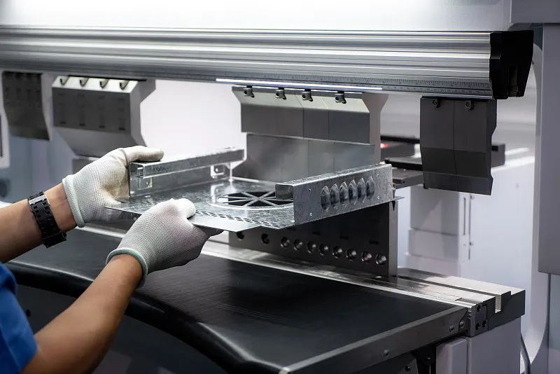
Prototype parts are typically laser cut from flat sheet, formed on a press brake, and then fitted with inserts, rivets or weld studs before finishing.
Laser cutting produces the flat pattern with clean edges and no tooling cost, which is why it dominates prototype work: design changes cost nothing more than a new program. Where a part needs many identical holes, punching becomes economical at higher quantities, and the choice between the two is a volume decision rather than a quality one.
Forming happens on a press brake, where the part is bent between matching tools. The bend radius available depends on the tooling, and springback means the machine over-bends slightly so the material relaxes into the intended angle. Where the design specifies a radius that the shop does not have in tooling, the nearest available radius is used, which changes the flat pattern and the appearance of the corner.
Assembly then adds the hardware the design needs: self-clinching fasteners, rivet nuts, weld studs or captive screws. These are inserted after forming, and each one requires a hole of the correct size and enough material around it. Specifying the hardware with its manufacturer and part number removes an ambiguity that otherwise shows up as an oversized hole in the first article.
Where the assembly includes welded components, the weld sequence matters for distortion, and the finishing plan has to account for weld dressing. Those requirements are best stated with the order rather than discovered during assembly.
What tolerance should a prototype drawing carry?
Looser than production, tight where it functions.
Prototype tolerances should reflect what the part must prove: tight on the interfaces that mate, and generous on dimensions that do not affect function or assembly.
The reason is that prototype work uses general fabrication processes rather than dedicated tooling. Laser cutting holds profile accuracy well, but forming introduces variation that depends on material, bend radius and operator setup. Applying production tolerances to a formed prototype creates rejections that have nothing to do with whether the design works.
A more useful structure is to separate the features. Cut features such as holes and profiles are covered by a general tolerance. Formed features, including bend angles and the position of features relative to a bend, carry a wider one. And the interfaces that must align with another component carry an explicit callout, agreed with the shop.
Where a callout is genuinely critical, saying how it will be measured closes the loop. The framework for those callouts, including general tolerance classes, is set out on 6CProto’s standards and tolerances page.
Which finishes belong on a prototype?
Enough to prove the appearance, no more.
A functional prototype often needs no finish beyond deburring, while a cosmetic prototype needs the production finish, because colour, texture and edge appearance cannot be judged from bare metal.
Three levels of finishing are common in prototype work. Deburring removes sharp edges and is enough for a part that will only be handled inside a workshop. A functional finish such as zinc plating, powder coating or anodising protects the part and allows it to be handled and tested in realistic conditions. A cosmetic finish reproduces the production appearance and is used when the prototype will be shown to customers or used for a design review.
The finishing choice interacts with the design. Coating thickness affects fits and thread engagement, so masked areas have to be specified before finishing. Anodising changes dimensions slightly and is dye-dependent. And any coating applied to cut edges behaves differently from the same coating on a formed face, which matters on galvanised material.
Specifying the finish per surface, as on a machined part, avoids the situation where a functional prototype is finished to a cosmetic standard at unnecessary cost, or a cosmetic prototype is left bare. Sheet metal fabrication and the associated finishing operations are run in the same facility, which keeps those decisions in one order. Where a coating has to be judged by appearance or by adhesion rather than by colour alone, the relevant test methods are published by standards committees such as ASTM committee B08 on metallic and inorganic coatings, with the surface preparation framework described in ASTM D3359.
What documentation should accompany a prototype?
Enough to support the design decision.
A prototype is more useful when it arrives with dimensional results on the critical features, the material and finish actually used, and a note of any deviation from the drawing.
The documentation does not need to be extensive. Dimensional results on the features that decide assembly, a record of the material grade and thickness, and the finishing steps applied are the core. Where the prototype deviates from the drawing, recording the deviation and its cause is more valuable than concealing it, because the deviation is often the information that informs the tooling decision.
For programs that will go to tooling, a first article inspection report provides the reference against which production parts are compared, and it establishes the acceptance method early. Where the prototype is developed through several iterations, the report from the final iteration becomes the design record.
6CProto reviews sheet metal models for manufacturability before production and provides quality inspection reports on request, with a dedicated project manager following each order, so the reporting scope can be agreed with the quote rather than after delivery. Where a process generates chemical waste, such as a plating or coating line, that waste is handled under the industrial framework published by the US Environmental Protection Agency.
What drives prototype cost and lead time?
Part count, forming complexity and finishing.
Laser cutting is fast and cheap per part, forming adds setup and handling, and finishing adds a separate process step, so cost depends on how many operations the design requires.
The first driver is quantity and how the parts are nested. Laser cutting is programmed once, so the cost per part falls as more components are cut from the same sheet, and small parts that nest efficiently are economical even in single figures.
Forming is the second driver. Each bend is a machine operation with handling time, and complex sequences require specific tooling and, sometimes, a custom fixture to hold the part at an angle. Designs that reuse the same bend radius across a part are cheaper to form than designs that require several different tools.
Finishing and hardware are the third. Powder coating, plating or anodising are batch operations with their own minimum handling, and each inserted fastener is a separate operation. Grouping several prototype parts into one order shares the setup across all of them, which is often the simplest way to reduce the cost of a design iteration. Requests submitted through the quote flow receive a manufacturability review before production, so forming and hardware decisions are visible before the parts are cut.
Getting a prototype that informs the decision
A sheet metal prototype is most valuable when it is specified for the question it is answering. If the question is whether the enclosure closes, then fit accuracy and assembly realism matter and the finish does not. If the question is whether the design can be manufactured at volume, then bend radii, hole sizes, hardware clearances and edge quality matter, and the prototype should be reviewed against production limits rather than treated as a one-off.
The specification that produces a useful result names the material and thickness, identifies the critical interfaces, states the finish per surface, and asks for dimensional results on the features that decide the outcome. Those four items turn a prototype from a model into evidence for the tooling decision, which is what the next stage of a program actually needs. The documentation conventions that support that evidence, including dimensional reporting practices, are described in the manufacturing guidance published by NIST MEP.
FAQ
How much does sheet metal prototyping cost?
Cost is driven by cutting, forming and finishing rather than by the material alone. Laser cutting is programmed once, so the cost per part falls with quantity and with how well parts nest on the sheet. Each bend is a separate machine operation, and finishing is a batch process with its own handling. Grouping several prototype parts into one order shares those setups, which usually has a larger effect on the price than changing the material.
How long does a sheet metal prototype take?
Lead time depends on how many operations the design needs rather than on the size of the part. A flat, laser-cut component requires programming and cutting. A formed part adds press brake setup for each bend radius used. Hardware insertion and finishing add further steps, each with its own queue. A design that reuses one bend radius and avoids welding will move through the shop faster than one requiring several tools and a finishing sequence.
Can a prototype be made from a different material than production?
It can, and it is sometimes the practical choice for a quick form check, but the substitution has to be recorded and its effect understood. A different alloy changes stiffness, weight, springback and forming behaviour, so a prototype in a substitute material does not validate structure or transfer its flat pattern. Where the test involves load, weight or forming limits, prototyping in the production material is the reliable route.
How accurate are sheet metal prototypes compared with production parts?
Cut features are usually accurate, because laser cutting follows a programmed path. Formed features vary more, because bend angle depends on material behaviour and on how the machine compensates for springback. Production stamping achieves tighter and more repeatable results once the tool is proven. For that reason, prototype tolerances should be set around what the part must prove, with tight callouts reserved for the interfaces that mate with other components.
If a sheet metal design is heading for tooling, send the flat model with the interfaces that must line up and the finish each surface needs. 6CProto reviews sheet metal parts for manufacturability, runs cutting, forming, hardware insertion and finishing in the same facility, and returns a DFM report with the quote. Upload the file at the 6CProto quote page or send it to projects@6cproto.com.