

Powder bed fusion covers the family of processes that build parts by melting or sintering powder layer by layer. It is the route to functional nylon parts with no support marks and to metal parts with internal geometry no cutter can reach, and its limitations are just as specific as its strengths.
What the process family includes
The two branches that matter commercially are laser sintering of polymers, usually nylon, and laser powder bed fusion of metals. Both spread a thin layer of powder, fuse a cross-section, and repeat. Because the unfused powder supports the part, no dedicated support structure is needed in the polymer version, which is why SLS and MJF parts come out with a uniform surface and no witness marks where supports were removed.
| Process | Material | Best suited to |
|---|---|---|
| SLS (laser sintering) | Nylon PA12 and filled variants | Functional prototypes and small-batch end-use parts |
| MJF (multi jet fusion) | Nylon PA12 and PA11 | Similar parts where throughput and consistent properties matter |
| Laser powder bed fusion (metal) | Stainless, aluminium, titanium, nickel alloys | Complex internal geometry and consolidated assemblies |
What are the disadvantages of powder bed fusion?
Texture, porosity, size limits and cost at low volume.
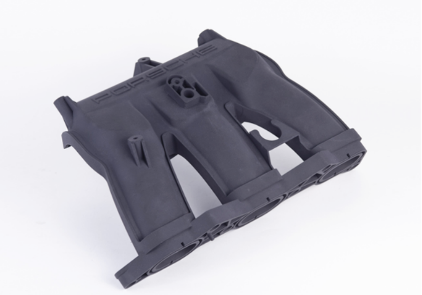
The parts come out grainy, because the surface is defined by powder particles rather than by a cutter. That texture cannot be sanded away as easily as resin layer lines, so a part needing a smooth or sealing surface will need machining afterwards. Polymer parts are also slightly porous, which rules them out for anything that must hold pressure or be cleaned to a high standard.
Two further limits matter commercially. Unfused powder has to be removed from internal channels, so a design with blind pockets and no escape route may not be producible as drawn. And because the build chamber is a fixed cost per run, a single small part carries the whole machine time; the economics improve only when parts are nested together, which is why the process favours batch orders.
How much does powder bed fusion cost?
Machine time and build height dominate, not volume alone.
A build occupies the chamber for its duration, so the price reflects how much of the machine the job consumes rather than the weight of the finished part. Height matters most, because build time scales with the number of layers. That is why a tall, thin part can cost more than a shorter part of greater volume, and why nesting several designs into one build is the single largest cost lever available.
Material adds a second line, and in the metal version it is significant because powder is consumed in supports as well as in the part. Post-processing adds the rest: powder removal, support removal on metal parts, surface finishing where appearance matters, and machining of controlled faces. An enquiry that states the quantity and whether parts can be batched will receive a more useful figure than one that sends a single part for a one-off price.
Design rules that suit the process
Powder bed fusion is generous with complexity but has a few firm rules. Walls should be thick enough to survive powder removal and handling, and thin sections that are unsupported across a large area will warp as they cool. Internal channels need a way for trapped powder to escape, and long unsupported spans are more reliable when built at an angle rather than flat. Metal parts also need supports, so overhangs carry both a material cost and a hand-removal cost.
Two habits improve results. Orient long flat features diagonally to reduce warp, and consolidate several parts into one printed assembly only where the joints can be broken or finished afterwards, since a printed hinge or a printed sliding pair will not have the clearance of a machined joint. Process terminology is standardised through ASTM Committee F42, and qualification guidance for additive production is published by UL Solutions.
Materials and when each one fits
Nylon is the workhorse for polymer parts because it is tough, tolerates repeated handling and accepts inserts and threads cut after printing. Filled variants, such as those reinforced with glass or carbon fibre, increase stiffness and heat resistance at the cost of a rougher surface and more tool wear if the part is later machined. In metals, stainless grades suit general structural and corrosion-resistant parts, aluminium reduces weight, and titanium and nickel alloys serve high-temperature or high-strength applications where the cost is justified by the duty.
Material choice should follow the test the part has to pass. A housing that is handled and dropped calls for nylon; a fixture that must stay dimensionally stable under load calls for a filled grade or a machined metal alternative; a component exposed to heat and corrosion calls for a metal powder bed process, accepting the post-processing that comes with it. Material references are published by ASM International, and the process comparison is set out on the MJF and metal 3D printing pages.
Quality checks on a powder bed part
Inspection starts with the surface and the internal condition: loose powder removed from every channel, no partially fused material on a functional face, and no warp on long sections. Dimensional checks follow, focused on the features that carry the fit after any post-processing, since machining or finishing changes the dimensions that were printed.
For a metal part, the additional questions are about density and heat treatment, both of which affect mechanical behaviour rather than geometry and both of which should be confirmed rather than assumed. Measurement practice is described by the NIST Manufacturing Extension Partnership, application guidance is published by ASME, and powder handling and waste obligations by the US EPA. Where a part needs a smooth or sealing surface, the route back to a cut surface is described on the CNC machining pages.
Send the model with the quantity and the surfaces that must stay smooth, and request a powder bed fusion quote with nesting confirmed.
FAQ
What are the disadvantages of powder bed fusion?
A grainy surface, slight porosity on polymer parts, trapped powder in blind channels, and a cost structure that penalises single small parts because the build occupies the machine for its full duration. Machining is usually needed where a smooth or sealing surface is required.
What materials can be used in powder bed fusion?
Polymer versions use nylon, including filled grades reinforced with glass or carbon fibre, while metal versions use stainless steels, aluminium, titanium and nickel alloys. Material choice follows the test the part has to pass rather than the price alone.
Does powder bed fusion need support structures?
Polymer processes do not, because the surrounding powder supports the part. Metal processes do, to anchor overhangs and conduct heat away, and those supports are removed by hand, which adds both material and labour to the price.