

What Automotive Plastic Parts Deliver
Automotive plastic parts are molded or fabricated polymer components used in interiors, exteriors, and functional systems to reduce weight, improve performance, and lower cost. They are produced by injection molding, CNC machining, 3D printing, or thermoforming, and the material and process choice is driven by load, temperature, chemical exposure, and durability requirements. The performance case is straightforward: lower weight improves fuel economy or electric range, integrated plastic designs reduce assembly time and parts count, and polymer components damp vibration and noise while resisting corrosion.
Plastics also take over mechanical roles that metals used to own. Injection-molded under-hood housings survive high temperatures with dimensional stability, exterior trim flexes under impact rather than fracturing, and ducts and brackets consolidate several metal parts into one component. Engineering teams typically replace a metal part with plastic when the weight and integration benefits outweigh the material and tooling costs, and the decision is validated with analysis and durability testing before release.
Materials and Their Applications
| Material | Strengths | Typical use |
|---|---|---|
| Polypropylene (PP) | Low cost, good impact | Interior trim, battery cases, bumpers |
| Polyamide (nylon) | High strength, heat/chemical resistance | Under-hood parts, connectors, fluid housings |
| Polycarbonate (PC) | Clarity, impact strength | Headlamp lenses, transparent covers |
| ABS | Strength, stiffness, surface quality | Interior panels, instrument clusters |
| PBT / PC-PET blends | Flame resistance, UV stability | Electrical housings, connectors |
Selection is often governed by OEM specifications, SAE standards, and internal test data, and real projects compare candidate materials with thermal cycling, vibration, chemical exposure, and crash-related validation. The injection molding materials page lists the practical grades for production-intent parts.
Process Choices Across the Development Stages
Early concept models use 3D printing for fast form and fit checks; functional prototypes that must mimic production behavior are machined from engineering plastics or made by short-run molding; and final validation builds use production-representative processes. A typical program is hybrid: printed concepts for the first iterations, CNC-machined prototypes for functional validation, and short-run injection-molded parts for crash, durability, and pre-production testing. The process should follow the stage, and a single partner that offers 3D printing, CNC machining, and injection molding keeps the transition between stages clean.
DFM for Molded Automotive Parts
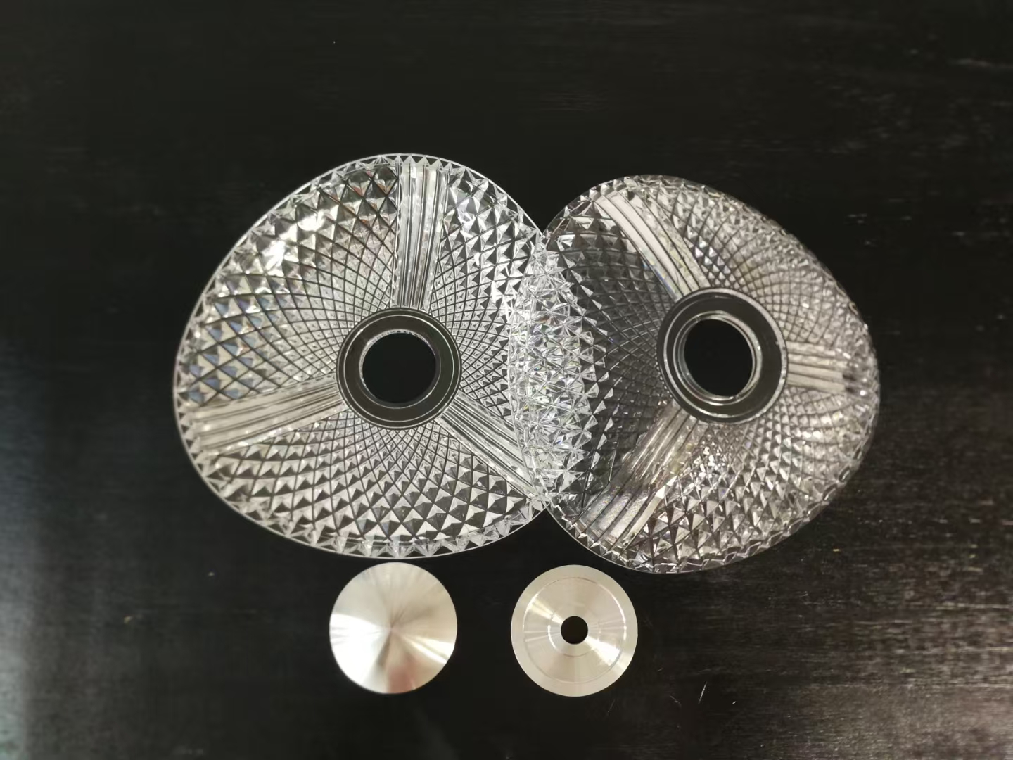
Design for manufacturing directly influences cost, quality, lead time, and the ability to meet tight tolerances and regulatory requirements. Wall thickness uniformity avoids sink marks and warpage; ribs and bosses add stiffness without mass when sized and positioned correctly; fillets reduce stress and improve flow; and a realistic tolerance strategy matches the material and process capability. Gating, venting, and ejection must be confirmed so the cavity fills cleanly without short shots or air traps. Teams that run DFM reviews early adjust corner radii, local thickness, and mounting points before the tool is cut, which is where the largest cost and schedule savings live. The DFM checklist and the mold flow analysis guide cover the review in practice.
Quality, Certification, and Traceability
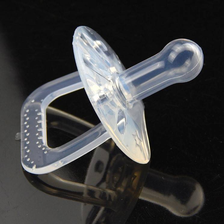
Automotive quality requirements dictate the inspection methods, documentation, traceability, and acceptable defect levels. OEMs and Tier-1 suppliers typically require ISO 9001 quality management and often IATF 16949 for automotive-specific processes, plus material certifications and test reports. The practical package includes dimensional inspection with CMM or optical systems on critical features, resin grade and additive documentation with UL or flame ratings where required, controlled process parameters, lot traceability from raw material to finished part, and functional testing, durability, vibration, thermal cycling, and chemical exposure, as applicable. For prototype and low-volume buyers, the same records support the transition to production because the process evidence transfers with the part.
Choosing a Supplier for the Lifecycle
Supplier selection should weigh technical capability, quality systems, lead time, and the ability to support the full lifecycle. A partner that handles both prototyping and production reduces handoff risk and communication overhead, and one that reviews the actual geometry, returns a process plan, and names the inspection points behaves like an engineering resource rather than an order desk. Confirm the documentation the supplier can produce, the change-control rules, and the engineering review cadence before the program starts. Standards such as NIST measurement practice provide the reference for how tolerance results are verified, and the automotive industry page shows the production envelope for molded and machined vehicle components.
Prototype-to-Production Transition for Plastic Parts
The transition from a machined or printed prototype to a molded production part is a process change, not a geometry copy. The same wall thickness that mills cleanly may not fill in molding; ribs that were strong in a machined part can sink in a molded one; and the gate location decides which surface carries the flow marks. The pre-production stage exists to catch these differences: build the part with production tooling, confirm the fill and the finish, and measure the critical dimensions before volume. A pilot run then exposes variation in the process, the tolerances, and the assembly before the full release.
The documentation should survive the transition. Material certificates, dimensional reports, and process parameters belong to the part ID and should carry into production, so the qualification work done on the prototypes is not repeated. Defining change control, what triggers revalidation, protects the qualified state when the mold is adjusted or the resin lot changes. The release sequence described here is what lets a fast prototype become a durable SKU, and the same logic applies whether the program starts in rapid prototyping or enters directly at low-volume production.
Cost Structure of Molded and Machined Parts
The cost profile of a plastic automotive part is decided by the process as much as the design. Machined parts carry a moderate fixed cost and a high variable cost, which favors small quantities; molded parts carry a large fixed tooling cost and a low variable cost, which favors volume. The crossover depends on the part size, the material, and the expected life of the program, and it should be calculated with the full program volume rather than a single unit price. Secondary operations, painting, texture, and assembly features move the comparison, so the quote should separate the tooling, the per-part cost, and the finishing cost.
For teams comparing routes, the injection molding quote guide explains how the tooling and unit costs are presented, and the molding service pages show the capability ranges that set the realistic crossover point. Keeping the quantity, the design revision, and the finish specification in the RFQ lets the supplier quote the right process instead of padding for unknowns.
Testing That Matters for Automotive Plastic
The tests should follow the application. Interior parts are judged on surface quality, color stability, and fogging; under-hood parts on heat aging and chemical resistance; exterior trim on UV stability and impact; and structural or crash-adjacent parts on the vehicle-specific load cases. Thermal cycling, vibration, and chemical exposure cover the operating envelope, and the material grade and process must be qualified together with the test, because a change in either can invalidate the result. For prototypes, the test should be representative of the production grade and process, which is why short-run molded parts, not prints, carry the final validation.
Design Checks Before the Mold Is Cut
The design checks that prevent molding defects are known and cheap to apply. Keep wall thickness uniform to avoid sink marks and warpage; size ribs at roughly half the nominal wall thickness and space them to avoid local thickening; add draft to every vertical face so the part releases without scuffing; and place the gate on the least visible surface or design it for easy trimming. Corner radii improve flow and reduce stress concentration, and bosses should be connected to the wall with ribs so they do not sink. Running these checks in the DFM review converts most project risk into a fixed design.
For the parts that cannot satisfy the checks, the review should name the alternative: a gate relocation, a side action, a thicker wall, or a different material with better flow. The complex parts guide and the tolerance guidance extend the same logic to machined and inspected features, keeping the whole program on one quality vocabulary.
Common Mistakes to Avoid
Most automotive plastic program failures share a short list of causes. Selecting the material from a brochure without thermal or chemical validation; treating a printed prototype as proof of production behavior; skipping the DFM review until after tooling; and failing to lock the revision before the mold is cut. Each mistake costs time and money in proportion to how late it is found. The corrective habit is the same: validate the material and process at each stage, review the geometry early, and freeze the design before spending on tooling. The supplier’s DFM feedback is the cheapest line in the program budget, and the review is only useful when it is specific to the geometry, material, and tolerance callouts.
FAQs
How long does an automotive plastic prototype take?
Printed concept models can arrive in days, machined prototypes in a few days to a week, and short-run molded parts in weeks once tooling is available. The stage and the required fidelity drive the lead time.
Can automotive plastic prototypes be used for functional testing?
Yes, if they are made by a production-representative process from the intended material grade. Printed parts can validate form but not production material behavior; machined or short-run molded prototypes are the functional tests.
What are the common mistakes when designing automotive plastic parts?
Non-uniform walls, undersized ribs and bosses, sharp corners, unrealistic tolerances, and gating that does not match the visible surface. DFM review before tooling is the standard fix, and the injection molding quote guide frames the cost side of the same decisions.