By 6CProto Engineering Team · Updated August 15, 2026
DFM, or design for manufacturability, is the review that finds geometry, tolerance, material, and finishing issues before the part is machined. A good DFM review for CNC parts checks tool access, wall thickness, internal radii, tolerance realism, datum strategy, and stock availability, and it returns actionable feedback instead of a price. The goal is not to redesign your part, but to catch the features that will cost time and money if they reach the machine unchanged.
Why DFM Matters More Than the Quote
The quote reflects the drawing as it is. A DFM review reflects the drawing as it could be, and the difference between the two is where cost and lead time hide. A deep pocket that needs a long tool, a tolerance that the geometry cannot hold, or a thin wall that will deflect can each multiply the price.
Suppliers that review the drawing before quoting tend to flag these issues early, when they are cheap to fix. Suppliers that quote without review often absorb the risk, then recover it in rework, inspection, or change orders.
Ask for DFM feedback as part of the quote. A response that lists risks and suggested changes is more useful than a low price, because it shows the supplier actually read the drawing.
Stage 1: Geometry and Tool Access
Start the review with the features a cutter must reach. Check internal radii, which should be as large as practical, because small radii force small tools that deflect and cut slowly.
Check wall thickness and pocket depth. Thin walls vibrate and deflect, deep pockets force long tools, and the combination multiplies the risk. If a wall is under roughly 0.5–1 mm, depending on material and depth, confirm it can be machined before quoting.
Check threads and small features for tool reach. Deep threaded holes, tiny slots, and features in hard-to-reach corners may need specialty tooling or an extra operation, and the drawing should show them clearly.
DFM by Feature Type
Pockets: keep the depth-to-width ratio reasonable and the internal radii as large as possible. Deep, narrow pockets force long tools that deflect and cut slowly.
Thin walls: confirm the wall can be machined without vibration. Ribs and walls below about 1 mm, depending on material and height, may need special strategies or a design change.
Threads and holes: specify the thread class and hole depth. Deep threads need extended tooling, and small holes in hard materials need the right drill cycle and coolant delivery.
Large flat faces: flatness on wide surfaces depends on fixturing and stress relief, so mark the surfaces that must stay flat and confirm the inspection method.
Stage 2: Tolerances and Datums
Review the tolerance callouts against the geometry. A tolerance that is routine on a short, stiff feature may be unrealistic on a thin wall or a long slender shaft, and the drawing should mark which dimensions are critical.
Review the tolerance-to-feature relationship for every critical callout. A tight tolerance on a short bore may be routine, while the same number on a long slender shaft may require grinding or special fixturing, and the drawing should reflect what the feature realistically needs.
Check the datum scheme. Mating features should reference the same datums that the supplier uses for fixturing and inspection, and a drawing without datums leaves the measurement open to interpretation.
Confirm that the critical tolerances are measured, not assumed. A positional tolerance without a datum, or a surface finish without a measurement method, cannot be verified, and an unverifiable callout is a dispute waiting to happen.
Stage 3: Materials and Stock
Confirm the material grade, temper, and form. Round parts use bar stock, prismatic parts use plate or block, and the available stock size can limit the part envelope or add cost for oversized material.
Check the material’s machinability against the geometry. Stainless work-hardens, plastics move with temperature, and hardened steels need specialized tooling, so the geometry and the material should be reviewed together.
Confirm the finish and treatment requirements early. Anodizing, plating, and coating change the final dimensions and surface texture, so the drawing should state the finish and whether tolerances apply before or after treatment.
Stage 4: Finishing and Inspection
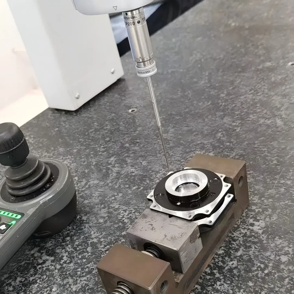
Review the inspection plan with the same attention as the machining plan. Critical features need a measurement method, and first-article inspection should cover the datums and instruments agreed in the quote.
Check secondary operations. Deburring, threading, polishing, and coating are real costs and lead-time items, and a complete quote should show them rather than leaving them implicit.
Confirm how revisions are handled. A version label on the drawing and a short change log prevent the wrong geometry from being machined, which is one of the most expensive DFM failures.
Ask for a clear statement of what is included in the price: deburring, inspection, reports, and finishing. The cheapest quote often excludes the steps that make the part usable, and comparing inclusive quotes prevents surprises.
What a Good DFM Response Looks Like
| Area | Weak response | Strong response |
|---|---|---|
| Tolerances | “Can hold ±0.05 mm” | Flags which features can’t, suggests achievable values |
| Geometry | “OK” | Notes tool reach, thin walls, internal radii |
| Material | No comment | Confirms stock, machinability, and finish effects |
| Inspection | “CMM available” | States which features are measured and how |
| Revisions | No policy | Documents version control and change costs |
Use the table as a scoring sheet when comparing suppliers. The quality of the DFM response is a strong predictor of the quality of the delivered parts.
Common DFM Wins
Some of the biggest savings come from small changes. Increasing an internal radius from 0.5 mm to 1 mm, relaxing a non-critical tolerance, adding a standard thread, or using a common stock size can cut cycle time without changing function.
Ask the supplier to list the top three changes that would reduce cost. A supplier that answers with specific, engineering-based suggestions is demonstrating the DFM process, and the suggestions are usually safe to review with your design team.
Common Misconceptions
- DFM means redesigning my part. It means flagging cost and risk drivers and suggesting alternatives that preserve function, not changing the design for its own sake.
- Tighter tolerances are always better. Every tight callout adds cost and inspection risk. Tolerance only the features that affect fit, function, or assembly.
- The quote is the only comparison. Compare the DFM feedback too, because the supplier that understands the drawing will deliver closer to it.
- DFM happens after quoting. The review is most valuable before the quote, when changes are free and the price still reflects them.
6CProto Expert Views
6CProto engineering perspective: Treat DFM as a design collaboration, not a formality. Send a drawing with critical features marked and datums defined, and ask the supplier to flag tool reach, thin walls, tolerance risks, and finish effects before quoting. The feedback is free; the rework it prevents is not.
Conclusion
DFM for CNC machining is the review that catches geometry, tolerance, material, and inspection issues before they reach the machine. Check tool access, wall thickness, internal radii, tolerance realism, datum strategy, material selection, and finishing early, and ask suppliers to return their findings with the quote.
Send a complete drawing with critical features marked, datums defined, and the finish specified, and compare the DFM responses as carefully as the prices. The supplier that reads the drawing carefully is the one that will machine it correctly.
FAQs
What does DFM stand for in machining?
Design for manufacturability. It is the review of a part design against the capabilities and limits of the machining process, done before production to reduce cost and risk.
How much does a DFM review cost?
It is usually included with the quote or available on request. A quality DFM review saves more in avoided rework and changes than it costs, so ask for it before ordering.
What are the most common CNC DFM issues?
Deep pockets requiring long tools, thin walls that deflect, small internal radii, unrealistic tolerances, missing datums, and finishes specified without measurement methods.
Should I send a drawing or just a CAD file?
Send both when possible. The CAD file gives the geometry, and the drawing carries the tolerances, datums, material, and finish, which are the information DFM actually reviews.
Can DFM reduce my part cost?
Often yes. Increasing internal radii, relaxing non-critical tolerances, and simplifying deep features can cut cycle time and tooling cost without changing function. Ask the supplier to name the top cost drivers on your drawing, because the highest-impact changes are usually a handful of features, not the whole design.
Sources
- 6CProto CNC Machining Services
- 6CProto CNC Machining Tolerances
- ISO 2768-1:1989 – General tolerances
- ISO 9001:2015 – Quality management systems