

Mold flow analysis, also called injection molding simulation or plastic flow simulation, predicts how molten resin fills, cools, and solidifies inside a mold cavity before any steel is cut. Done well, it converts a plastic part design into a reliable mold and a repeatable process, flagging short shots, air traps, weld lines, and warpage risks while changes are still cheap. Done poorly, it adds a colorful report that the production floor quietly ignores. The difference is input discipline: simulation results are only as trustworthy as the CAD data, material model, and process assumptions behind them, and the output only earns its keep when it is linked to T0/T1 samples and inspection.
What Is a Mold Flow Analysis?
Mold flow analysis is a software simulation that models resin behavior, cooling, and pressure distribution during injection. The process starts with a 3D CAD model of the part, then adds material properties, mold geometry, gate locations, and process parameters. The outputs predict fill time, pressure distribution, temperature fields, potential defects such as shorts, voids, weld lines, and air traps, and expected warpage or dimensional shift.
The benefit is timing: engineers can optimize gate and runner design, adjust wall thickness, reposition cooling channels, and refine the process window before committing to tooling. The constraint is just as important: results depend on accurate material data, geometry, and process assumptions, and real-world validation with trial shots is still required. Mold flow analysis reduces the number of mold iterations; it does not remove the need for the first one.
Why Mold Flow Analysis Is Harder Than It Looks
The failure modes of simulation are not exotic. Four of them show up repeatedly, and each one traces back to a bad input rather than a bad solver.
Incomplete or Inaccurate CAD Data
Simulation quality is directly tied to input geometry. Missing features, unrealistic tolerances, or simplified wall thicknesses produce misleading fill patterns and warpage predictions. If the CAD does not reflect the intended part, including rib locations, bosses, fillets, and draft, the analysis validates a part that does not exist. Fix the model before you simulate, or the report is fiction.
Process and Material Mismatch
Different resins have distinct viscosity, thermal, and shrinkage behavior. Using generic material data instead of manufacturer-specific data can mask residual stress and dimensional instability, so the fill pattern looks fine while the actual resin would knit, sink, or warp differently. The material grade on the simulation must match the grade on the purchase order, including lot-specific viscosity when the application demands it.
Over-Specified or Unrealistic Tolerances
Injection molding naturally introduces variation through shrinkage, warpage, and tooling wear. When a designer specifies ultra-tight tolerances without accounting for that variation, simulation can show acceptable results that still fail in production. Mold flow analysis highlights warpage risk, but it cannot guarantee that a tolerance will hold across every part without additional process control and inspection, so the drawing must separate what the process can reliably hold from what needs secondary operations.
Prototype-to-Production Transfer
A part that works as a CNC prototype or 3D-printed sample may behave differently when molded. Wall thickness, rib design, and gate location are secondary in machined parts and decisive in molding. Mold flow analysis bridges that gap only when it runs with production-grade assumptions, not prototype assumptions, which is why the analysis belongs before tooling, not after the first bad batch.
The DFM Link: Using Simulation to Ask Better Questions
Custom-part sourcing is not only about unit price or the tightest published tolerance. Clear drawings, realistic critical dimensions, process-material fit, inspection planning, and change control determine whether a prototype can move into repeatable production. Mold flow analysis shifts the discussion from “can we make this part?” to “how can we make it reliably, with predictable quality and cost?” That is the real output of the exercise: a process decision, not a picture.
For that reason, mold flow analysis is best run inside a broader DFM review rather than as a standalone deliverable. When the injection molding service team at 6CProto reviews a part, the simulation results inform material selection, gating strategy, and the tolerance and inspection plan together, so the mold is designed around a process that can actually produce the part. Buyers get the same value when they bring a clean drawing and realistic quantities to the injection molding quote review, because the quote then reflects the process rather than a list of unit prices.
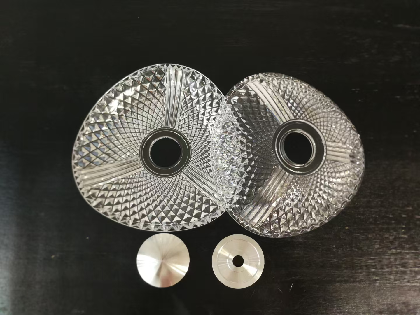
What Mold Flow Analysis Actually Changes in the Mold
The practical edits that simulation supports are specific and measurable. Gate location moves to fill the cavity uniformly and avoid weld lines in structurally loaded zones. Wall thickness is adjusted to balance flow lengths and prevent sink marks above bosses and ribs. Cooling channel layout is revised to even out temperature fields and shorten cycle time without distortion. Venting is placed where air traps are predicted. Each of these edits is verifiable at trial: fill shorter than expected, weld line in a low-stress location, flatness within the agreed window. The simulation is effective when it shortens the T0-to-approval loop, not when it produces a thick binder.
The other thing simulation changes is the inspection plan. If warpage is predicted near a critical interface, that surface gets measured; if gate trimming affects a cosmetic face, the part is checked there too. That is the connection between analysis and inspection frameworks, the same discipline that NIST applies to measurement assurance and uncertainty: the simulation tells the quality team where to look, and the measurements verify the prediction.
From Prototype to Production Without a Surprise
The transfer from CNC prototype or printed sample to molded production is where most projects lose time, because the geometry that was trivial to machine becomes a molding constraint. A wall that is too thin for the resin to fill, a rib without draft that sticks in the mold, a gate in a cosmetic zone, all of these surface at the first trial unless the design review catches them. Mold flow analysis is one part of that review, alongside draft analysis, wall balance checks, and gate placement rules. The sequence that works is: clean up the CAD, run the simulation with production-grade material data, apply the edits, then validate with trial shots and measure the parts against the agreed tolerances.
For rapid prototyping and low-volume runs, the same discipline applies at smaller scale. Tooling is still being committed, and a simulation that catches one redesign is worth more than the entire analysis fee. The mold flow conversation should start with a question: what is the biggest risk on this part, fill, warpage, or dimensional stability? The analysis that answers that question first is the one that earns its place.
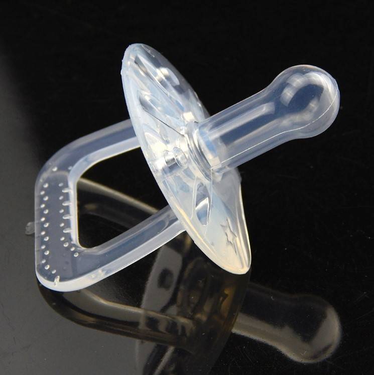
What Engineers and Buyers Should Prepare
- Final CAD with ribs, bosses, fillets, and draft, not a simplified shell.
- Material grade confirmed against the manufacturer’s data sheet and viscosity model.
- Realistic tolerance callouts split between process-held and inspected dimensions.
- Target quantity and gate/cosmetic zone preferences, which drive runner and gate design.
- Agreement on validation: T0/T1 samples, which dimensions get measured, and what triggers a mold edit.
When those inputs are clean, mold flow analysis becomes a decision tool instead of a formality. For teams comparing injection molding materials or deciding between prototyping routes, the FDM vs SLA vs SLS guide and the 3D printing materials page cover the options that precede tooling.
Frequently Asked Questions
Is mold flow analysis required for every injection-molded part?
No. Simple geometries with proven material and a standard process window can proceed directly to trial. The analysis earns its cost when geometry is complex, tolerances are tight, or the material is new to the team, and it is recommended as part of DFM review for those cases.
What tolerances are achievable with injection molding?
Achievable tolerances depend on part geometry, size, material, process, finish, and inspection requirements. 6CProto’s tolerance guidance distinguishes general, feature-specific, and quoted tolerances, and it should be reviewed per project rather than assumed.
How does DFM and quotation work?
Submit the RFQ with CAD, drawings, material, quantity, tolerances, and finish. Engineers review manufacturability, recommend mold flow analysis where geometry and quantity justify it, and return a process plan, quotation, lead time, and inspection approach. The injection molding service page describes the full workflow.
What is the difference between lead time and shipping time?
Production lead time covers tooling and cycle time; shipping transit time is delivery after production. Total delivery is the sum of both, and the quotation states them separately so project planning is not surprised.
Conclusion
Mold flow analysis reduces injection molding risk when the inputs are honest: clean CAD, real material data, realistic tolerances, and a clear link between simulation and trial validation. It is most valuable as part of a DFM and quality workflow that spans concept prototype, pilot, and production, and it pays for itself the first time it catches a redesign that would have waited for a full mold. Plan the analysis with the same discipline as the part itself, and the mold will be cut for a process that works.