

What a Surface Finish Standard Is For
A surface finish standard is a documented set of definitions, symbols, measurement methods, and acceptance criteria that describe the texture of a part’s surface. It lets engineers, manufacturers, and inspectors communicate roughness, waviness, and other micro-geometric features in a consistent way. Without it, “smooth” means one thing in design and another on the shop floor, and the inspection report becomes a matter of opinion.
Surface finish affects assembly, wear, corrosion resistance, electrical contact, sealing, and long-term reliability, so the standard exists for functional reasons as well as cosmetic ones. In practice, a finish standard lets you write “bearing surfaces Ra not exceeding 0.8 micrometers” or “external cosmetic surfaces N7” and have the supplier interpret and verify that requirement consistently across prototypes and production runs.
The Core Parameters: Ra, Rz, and the Rest
Roughness is described by a small set of parameters, and the two that dominate engineering drawings are:
- Ra (average roughness) is the arithmetic average of the surface profile’s deviation from a mean line. It is the most common specification because it is easy to measure and compare, and it describes the general finish class, from rough blasted surfaces to polished ones.
- Rz (peak-to-valley height) captures the vertical distance between the highest peak and the deepest valley over the evaluation length. Because it is sensitive to single events, scratches and pits, Rz matters for sealing faces, wear surfaces, and anywhere a single peak defeats the function.
Beyond Ra and Rz, waviness (W) describes longer-wavelength surface undulations, and lay describes the dominant direction of the surface texture left by the process. Both matter in specific applications: waviness affects optics and bearing contact, and lay affects sealing and lubricant retention. “Surface finish” is not one number. The specification should name the parameter, the value, the evaluation length, and the filter settings used to measure it.
The Standard Families and What They Cover
Finish standards come from several families, and each defines symbols, grades, and measurement protocols:
- ISO 4287 is the international reference for surface texture parameters, defining Ra, Rz, and the filter and evaluation conditions.
- ASME B46.1 is the American standard for surface texture, with symbols and measurement practice that appear widely on machining drawings.
- ISO 1302 and related drawing standards govern how finish symbols appear on a technical drawing, so the specification survives translation to the shop floor.
- Process-specific standards cover coatings and finishes, such as paint, anodizing, and plating, each with adhesion, thickness, and appearance criteria.
Where to measure is part of the same discipline. Roughness on a flat face, a bore, a threaded zone, and a formed edge is measured on different evaluation lengths, and the value changes with the cutoff filter. A drawing that specifies Ra without naming the location, direction, and evaluation length leaves the inspector to choose, and two inspectors can produce different numbers from the same part. The specification should therefore state the measurement direction relative to the lay, because roughness measured across the lay differs from roughness measured along it.
`n
The value of a named standard is not the document itself but the shared measurement practice it implies. “Ra 0.4” without a standard and a measurement condition is ambiguous; “Ra 0.4 per ISO 4287 with a 0.8 mm cutoff” is a specification. The current editions of these standards can be verified through the organizations that maintain them, and the US documentary standards system for surface finish terminology is maintained through NIST (NIST).
Matching the Finishing Process to the Material
Every manufacturing process leaves a characteristic surface, and the finish specification must be compatible with both the process and the material:
- Machined surfaces start with tool-mark texture, typically in the Ra 0.4 to 3.2 micrometer range for standard machining, and reach lower values through polishing or fine grinding when the part requires it.
- Turned parts carry a circumferential lay from the tool path, which is fine for many seals and bushings if the direction is acceptable.
- Anodizing applies to aluminum, grows a controlled oxide layer, and changes the surface character and sometimes the dimensions, so it pairs with a defined base roughness.
- Plating and coatings cover the base finish, so the roughness that matters is the final coated surface, and thickness and adhesion become part of the specification.
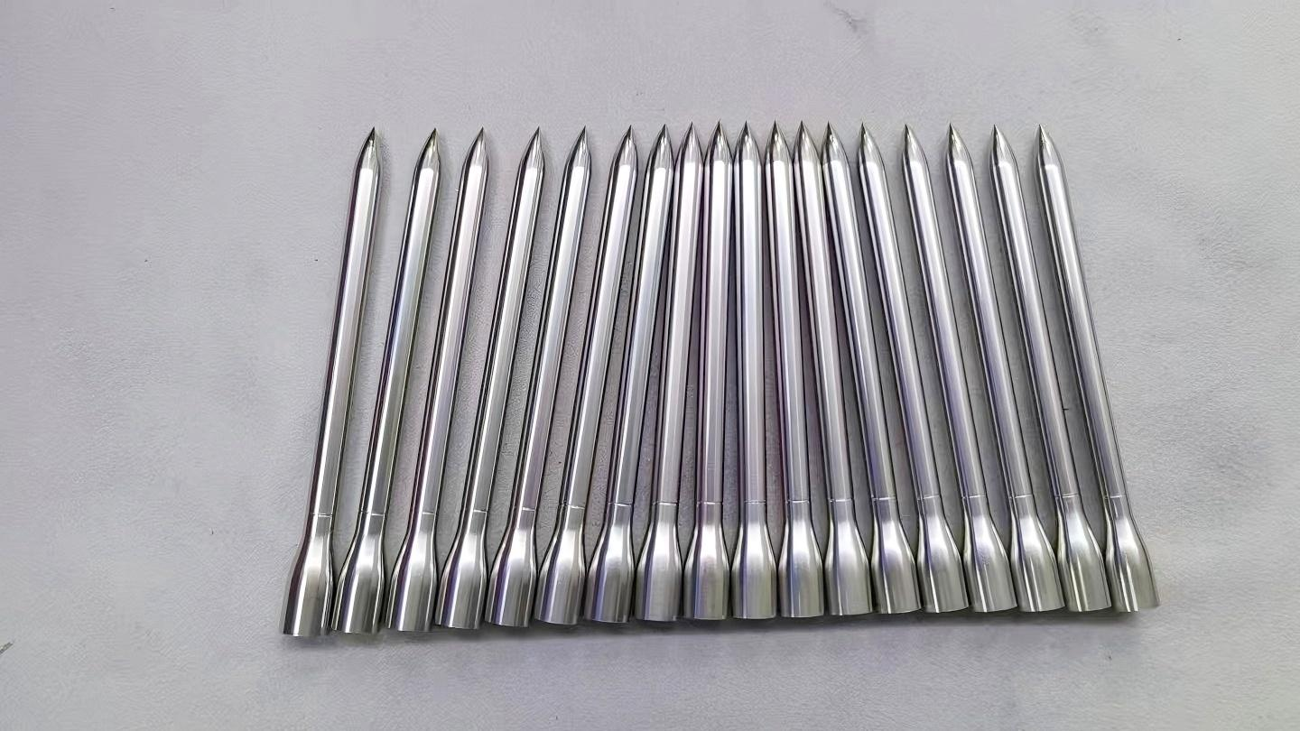
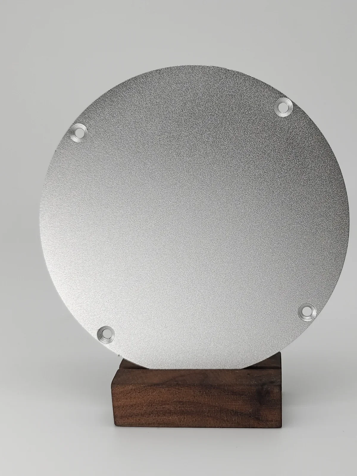
- Abrasive blasting sets a controlled matte texture and is compatible with metals and many plastics, but the resulting Ra is process-dependent and should be verified on a sample.
Some finishes are restricted to specific materials, and asking for the wrong combination produces failed inspections regardless of the number on the drawing. Confirm material and finish compatibility during design-for-manufacturing review, before the quotation locks the route.
Where Finish Specifications Go Wrong
The failures are remarkably consistent across RFQs, and each is avoidable with a controlled drawing:
- Missing surface definitions. The 3D model is sent without a 2D drawing, so no one knows which surfaces are cosmetic, which are functional, and what roughness each accepts. The manufacturer guesses, and the guess costs money.
- Process-material mismatch. A mirror finish on machined aluminum is achievable; the same number on a molded plastic part may be unrepresentable or unstable with the chosen finish. The finish must be chosen with the process, not after it.
- Over-specification. A single tight Ra value applied to the whole part multiplies cost on surfaces that do not need it. Roughness values should be assigned per surface zone: tight on sealing and bearing faces, practical on structural zones, and cosmetic classes on visible surfaces.
- Cosmetic and functional conflict. Premium appearance on exterior surfaces and tight functional finish on internal faces are different requirements with different evidence. They belong as separate callouts on the drawing, not one finish for everything.
One habit fixes most of these: annotate the drawing with finish callouts by surface zone, name the standard and parameter for each, and add a note that the sample bank is the reference for appearance. The drawing then carries the same information that the inspector will check.
Inspecting and Verifying Finish
A finish spec is only as good as the inspection behind it. Contact profilometry measures Ra and Rz along a line and is the workhorse for machined surfaces. Optical and laser methods cover softer or delicate surfaces without touching them, and roughness comparison specimens are used for quick floor checks where full measurement is not justified. Each method has a different cutoff and filter response, so the measurement method belongs in the specification, not just the target value.
Inspection samples and locations matter too. The drawing should state which surfaces are measured, how many locations, and what documentation ships with the parts. For appearance-driven finishes, the approved sample bank remains the reference and the roughness measurement is a supporting check. A finish that cannot be measured by the named method is a finish that cannot be accepted.
Putting Finish Specification Into Practice
6CProto applies this discipline in practice: the surface finishing services cover the process range from as-machined to brushing, sandblasting, polishing, anodizing, and coatings, and the CNC machining services page documents the base finishes that finishing builds on. The CNC machining materials page helps settle material and finish compatibility during DFM, and the article “CNC Machining Tolerances: A Practical Guide to What You Can Expect” maps typical finish and tolerance values to machined, ground, and polished states.
Finish interacts with the rest of the part specification in ways that belong on the same drawing. A sealing face that must also look uniform passes through a sequence, polish, then coordinate measurement, that differs from a structural face that is simply machined. Anodizing changes dimensions slightly and can blur a sharp edge, so features that must stay crisp after the coating should be flagged. And a finished surface stated as “per sample” carries no measurable roughness at all, so the sample should be paired with a written Ra or Rz value wherever the function depends on it. Each of these interactions is a drawing decision that prevents a finish dispute later.
`n
The finish class decision should also be part of the quotation review. Because the same finish can be achieved through different process routes at different costs, ask the supplier to quote the finish as specified, with a sample for appearance-driven work, and confirm the inspection method during DFM. That converts the finish from a wish into a measurable, verifiable requirement.
FAQ
Why would a manufacturer refuse a very low Ra value?
Because the geometry or material cannot hold it. A tight Ra on a thin-wall or flexible surface may be unrepresentable, and a single scratch that drives Rz up may be unavoidable in the chosen process. The practical answer is a DFM review that sets achievable values per surface zone rather than one number for everything.
What Ra can be expected from standard machining?
Standard machined surfaces typically start around Ra 3.2 micrometers, depending on material, tool, and feed, and reach finer values through grinding, polishing, or fine finishing. The achievable value depends on geometry, size, material, and inspection method, so confirm the target against the specific part during quoting.
Do I need to specify finish on every surface?
No, and applying one value everywhere is a common mistake. Call out finish only on the surfaces where function or appearance require it, sealing and bearing faces, wear zones, electrical contacts, and visible surfaces, and leave the rest to standard practice. That keeps cost and lead time where the part needs them.