

Explore Surface Preparation, Plating & Inspection
A drawing marked 125 can trigger an unnecessary polishing operation or an incorrect acceptance decision if the unit and parameter are missing. A shop may assume the familiar microinch convention, while the inspector reads a metric value or compares a different surface-texture parameter. The resulting numbers can look precise while describing different requirements.
A 125 surface finish callout commonly refers to 125 microinches Ra in a specified drawing convention, but the number alone is incomplete evidence of that meaning. Confirm the units, parameter, applicable standard and surface before approving the drawing or process. If 125 microinches is the intended value, it corresponds arithmetically to 3.175 micrometers; the conversion does not change the original acceptance rule.
This article focuses on interpreting that particular notation and establishing comparable measurements. It does not turn roughness into a universal prediction of sealing, wear or appearance, and it does not substitute an instrument’s default settings for the drawing requirement.
What units does a 125 surface finish callout use?
Confirm the drawing’s unit convention before interpretation.
A bare 125 can be ambiguous; where it denotes microinches Ra, record that unit and parameter explicitly rather than silently treating the number as a metric roughness value.
The Mitutoyo surface-texture guide separates parameters, units and measurement concepts. Use the drawing’s controlling standard and notes to establish how its notation is intended to be read. If that information is absent or contradictory, resolve the requirement before using the value to quote finishing work or reject parts.
The unit conversion itself is straightforward: one inch is 25.4 mm, so one microinch is 0.0254 micrometers and 125 microinches equals 3.175 micrometers. These are unit relationships, not a newly selected tolerance. Rounding the converted value should not silently tighten or relax the original limit. Preserve the original callout and its interpretation in the controlled drawing so different suppliers do not independently choose different conventions for the same functional surface.
If a historical drawing uses an unfamiliar symbol convention, preserve a controlled interpretation rather than relying on the current shop default. That interpretation should follow the part through supplier changes.
Distinguish Ra from other parameters
Ra is an average profile-roughness parameter; it is not interchangeable with a peak-to-valley parameter merely because both are expressed in length units. Surfaces with similar Ra can have different local peaks, valleys or lay, which can matter for their intended contact or sealing behavior.
The KEYENCE profile-parameter reference distinguishes the quantities. Do not convert between parameters using an assumed universal multiplier. A historical chart or shop rule may describe particular surfaces, but it does not establish an exact relationship for every manufacturing process or texture.
If the drawing controls Ra, the report should identify Ra and its units. If the function also depends on another parameter, define it through the appropriate engineering review rather than expecting Ra to represent the entire texture. This distinction is especially important when comparing a machined surface with a treated or textured one. Numerical similarity under one parameter does not prove that the surfaces will behave identically in the application, and a photograph cannot supply the missing quantitative definition.
Surface direction and measurement cutoff
A profile measurement depends on where and how the trace crosses the surface. The dominant lay, filtering and evaluated length can influence the reported result. Two instruments can therefore disagree without either being defective if they examine different texture content or use different settings.
The KEYENCE roughness-evaluation workflow explains the sequence of profile processing and evaluation. Keep the relevant settings with the result, including the standard or method used. A default instrument program is not automatically appropriate to every short land, interrupted surface or directional machining pattern.
For the 125 callout, identify the functional area and the intended measurement direction. Ensure that the available surface can accommodate the selected evaluation arrangement without crossing holes, edges or unrelated form. Where it cannot, agree on a suitable method and report the limitation explicitly. Changing the cutoff or shortening the evaluation solely to obtain a passing number changes the observation and should not occur without an approved acceptance basis.
Acceptance on the functional surface
A roughness callout should attach to the surface whose function requires it. Measuring an accessible neighboring face does not establish the condition of a recessed sealing land or a critical sliding surface. The drawing and inspection plan need to identify the actual area and any exclusions.
The standards and tolerances discussion should be linked to the controlling drawing requirement. Select measurement locations that represent the required surface, including relevant process variation, rather than only the most favorable visible region. Cleanliness, surface damage and handling can affect the ability to obtain useful measurements.
Keep roughness acceptance distinct from dimensional and functional acceptance. A land may meet its profile-roughness limit while being out of position or damaged at an edge. Conversely, a successful assembly trial does not prove that the specified texture was achieved. Where the application needs a functional test in addition to roughness measurement, identify both deliverables and the limits of each. This prevents one attractive result from being used to infer conformance in an unmeasured characteristic.
Define whether local scratches, dents or other surface damage are separately controlled. A profile average can pass while a localized defect remains unacceptable for the interface.
Parameter and acceptance-condition table
The number on the drawing becomes useful only when its associated conditions are known. The following table identifies the information required to make a 125 interpretation reproducible. It does not select a new standard or an instrument configuration for an unspecified surface.
Review these fields before production so a measurement disagreement can be traced to a defined requirement rather than resolved through repeated polishing.
| Field | Definition needed | Why it matters | Record location |
|---|---|---|---|
| Value and unit | Original callout and confirmed unit | Prevents microinch/metric ambiguity | Controlled drawing |
| Parameter | Ra or another specified quantity | Different parameters describe different features | Drawing and report |
| Evaluation setup | Applicable method, filters and length | Controls the texture content evaluated | Inspection instruction |
| Trace location | Functional surface and direction | Prevents substitution of an easier area | Inspection map |
| Acceptance rule | How results are judged | Avoids improvised pass/fail decisions | Approved specification |
The ASME drawing-standard overview provides context for controlled communication, while the actual project must identify the applicable surface-texture requirements.
Worked interpretation of a reported value
Assume an illustrative drawing explicitly requires Ra not greater than 125 microinches, and a report gives Ra = 3.0 micrometers using the approved method on the correct surface. Converting the stated limit gives 3.175 micrometers. On value comparison alone, 3.0 is below 3.175; the final disposition must still follow the agreed acceptance rule and measurement evidence.
Now suppose the report instead gives a different parameter at 3.0 micrometers. The numerical comparison is no longer sufficient because the quantities differ. Likewise, a result obtained using an unapproved cutoff or an adjacent surface cannot be accepted merely because the unit conversion is correct.
The Mitutoyo surface-roughness measurement resource supports the broader measurement context. Keep the example’s assumed requirement separate from the actual component drawing. The exercise demonstrates how to check parameter, unit and method before comparing numbers, rather than prescribing a roughness limit or suggesting that every 125 callout uses the same historical convention.
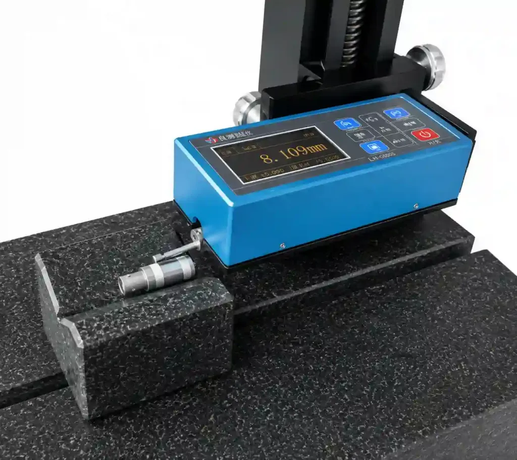
Measurement variability and limits
Repeated traces can differ because they sample different locations, directions or local features. Instrument condition, stylus geometry and setup also matter. A disagreement should therefore begin with the measurement definitions and raw observations, not an immediate conclusion that one party’s gauge is inaccurate.
Compare the reports for parameter, units, method, filters, evaluated length and location. Check whether the part changed through cleaning, finishing or handling between measurements. If the surface is directional, a changed trace direction can describe a different aspect of the texture rather than a change in manufacturing quality.
For a milled component, relate the inspection map to the toolpath and functional land without treating machining marks as a complete roughness measurement. Where a result lies close to an acceptance boundary, use the agreed decision rule and appropriate measurement review. Repeating measurements until one passes is not a valid substitute for understanding variability or documenting the condition of the delivered surface.
Retain the evaluated trace or supporting record where the acceptance plan requires it. A display photograph without location and settings may be insufficient to investigate a later disagreement.
Drawing and report notes for agreement
The released drawing should make the unit and parameter interpretation unambiguous and identify the controlled surface. The inspection instruction should carry the approved evaluation setup and reporting requirements. Keep those documents coordinated so a change to the measurement method does not silently alter the accepted product condition.
If a finishing proposal changes the surface texture or local dimensions, assess both effects before approval. The surface-finishing scope is relevant to that process discussion, but a named finish does not guarantee the required Ra or functional behavior. The specification must state the intended result and the evidence needed to accept it.
For repeat orders, retain the accepted inspection configuration with the part revision. A different instrument may be suitable if its method is appropriate, but the comparison needs a technical basis. The goal is to reproduce the required surface observation, not to preserve a particular display number while changing the conditions that gave the number its meaning.
When rework changes the surface, repeat the affected measurements using the approved setup. The original roughness result cannot describe material removed after it was recorded.
FAQ
Does a 125 callout require polishing?
The callout describes a required surface condition when its parameter and units are defined; it does not necessarily prescribe a particular finishing process. A suitable machining route may achieve the requirement, while another surface may need additional work. The supplier should select and verify an appropriate process against the controlled drawing. Do not add polishing automatically without considering dimensional changes, edge condition and the actual functional reason for the texture requirement.
Can a photograph establish compliance with 125 Ra?
A photograph can document appearance, damage or the location of visible marks, but it does not establish a quantitative profile-roughness value. Lighting and viewing conditions can make different surfaces appear similar or similar surfaces appear different. Use an appropriate measurement method for the numerical requirement and retain photographs as complementary evidence where useful. Cosmetic approval and measured roughness should remain separate acceptance decisions when the project controls both.
Should the converted value replace the original drawing number?
A controlled drawing revision can change units, but the conversion and rounding need to preserve the intended requirement. Do not silently replace the original number in a supplier report or informal markup. Record the original value and unit, the conversion basis and the approved interpretation. If different documents show inconsistent limits, resolve them through the design authority before production acceptance rather than allow each shop to choose the version it prefers.
Conclusion
The first acceptance question is what 125 means on the controlled drawing. Once the unit and parameter are confirmed, the measurement still needs the correct surface, direction and evaluation conditions. A unit conversion cannot repair a mismatch in any of those fields.
Keep that definition with the report and distinguish texture from geometry, appearance and function. This makes finishing proposals and measurement disagreements easier to evaluate without using unnecessary rework to chase an ambiguous number.
6CProto’s machining, finishing and DFM workflow can support the component review. Send the drawing with explicit roughness units, functional surfaces and inspection requirements for quotation, including any acceptance method that must remain fixed.
{“@context”: “https://schema.org”, “@type”: “FAQPage”, “mainEntity”: [{“@type”: “Question”, “name”: “Does a 125 callout require polishing?”, “acceptedAnswer”: {“@type”: “Answer”, “text”: “The callout describes a required surface condition when its parameter and units are defined; it does not necessarily prescribe a particular finishing process. A suitable machining route may achieve the requirement, while another surface may need additional work. The supplier should select and verify an appropriate process against the controlled drawing. Do not add polishing automatically without considering dimensional changes, edge condition and the actual functional reason for the texture requirement.”}}, {“@type”: “Question”, “name”: “Can a photograph establish compliance with 125 Ra?”, “acceptedAnswer”: {“@type”: “Answer”, “text”: “A photograph can document appearance, damage or the location of visible marks, but it does not establish a quantitative profile-roughness value. Lighting and viewing conditions can make different surfaces appear similar or similar surfaces appear different. Use an appropriate measurement method for the numerical requirement and retain photographs as complementary evidence where useful. Cosmetic approval and measured roughness should remain separate acceptance decisions when the project controls both.”}}, {“@type”: “Question”, “name”: “Should the converted value replace the original drawing number?”, “acceptedAnswer”: {“@type”: “Answer”, “text”: “A controlled drawing revision can change units, but the conversion and rounding need to preserve the intended requirement. Do not silently replace the original number in a supplier report or informal markup. Record the original value and unit, the conversion basis and the approved interpretation. If different documents show inconsistent limits, resolve them through the design authority before production acceptance rather than allow each shop to choose the version it prefers.”}}]}