

The first SLS part a team receives usually triggers the same two questions: why does it feel like fine sandpaper, and why does a hole that measured correctly on the drawing come back undersized? Neither is a production error. Powder-bed nylon has a characteristic surface and a set of geometric limits, and both are predictable once you know what the process does to a surface and where it stops resolving detail. This guide covers the as-built finish, the finishing routes that change it, the wall thickness and feature limits that keep a design inside the process, and the geometry decisions that control warpage.
What does an SLS part look like when it comes out of the build?
Matte, uniform, and slightly granular.
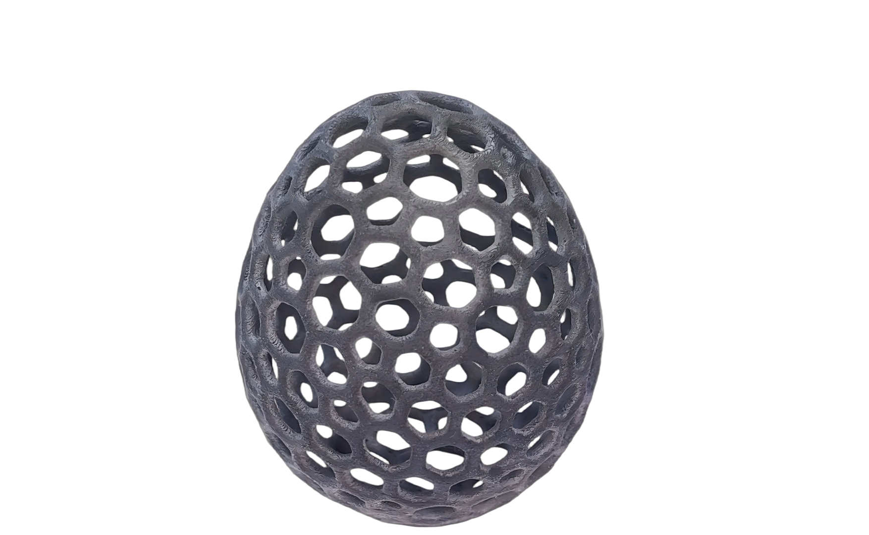
A fresh part carries a fine powder texture across every surface, including faces that were never supported, and it looks the same on all sides because nothing touches the part during the build.
The texture comes from the powder itself. Un-sintered particles sit against the outer skin of the part during the build, and where the laser energy reaches the boundary they partially fuse to it. The result is a uniform matte surface with a small, consistent grain, rather than the directional layer steps a resin or extrusion part shows.
That uniformity is an advantage in some applications and a limitation in others. Grip surfaces, fixtures, and hidden internal components look finished as they arrive. Cosmetic housings, sliding interfaces, and anything evaluated under a gloss standard do not, because the same surface that gives grip also scatters light and holds slightly more friction.
Colour is another as-built characteristic. Most nylon powders produce a light grey part, and the shade can vary slightly between builds because it depends on powder condition and on thermal history in the bed. Where a colour must be consistent across a batch, it is worth specifying dyeing rather than relying on the natural shade of the powder.
How do powder removal, blasting, and dyeing change the surface?
They clean, even and colour the surface, not smooth it.
Blasting removes caked powder and evens the grain, dyeing adds colour that penetrates the surface rather than coating it, and neither turns a nylon part glossy.
Powder removal is the first step and the one most likely to be underestimated on complex geometry. Loose powder has to escape from every internal volume, which is why a cavity with no opening is a design problem rather than a finishing problem. Blasting then cleans the outer surfaces and evens the texture, and it can be directed at specific areas where appearance matters more.
Dyeing works because nylon is porous enough to absorb dye into the surface layer. The colour is therefore part of the material rather than a film on top of it, which means it does not chip the way paint can, but it also means the final shade depends on the base powder, on part thickness, and on how the part was blasted before dyeing. Two identical parts from different builds can end up a shade apart, which is worth knowing before a colour match is promised across a program.
The surface finish guides cover the finishing routes available in the same facility, and the powder and property documentation published by platform suppliers such as EOS and 3D Systems describes the material behaviour behind them.
| Step | Effect on the surface | Effect on dimensions |
|---|---|---|
| Powder removal | Removes loose and caked powder from all faces | None, provided internal volumes can drain |
| Media blasting | Evens the grain, cleans discolouration | Slight edge rounding; negligible on flat faces |
| Dyeing | Adds colour into the surface layer | None measurable |
| Sealing or impregnation | Closes surface porosity | Can add a thin film on treated faces |
| Machining a face | Removes the grain entirely on that face | Deliberate material removal to a callout |
What wall thickness and feature sizes survive the powder bed?
Thin sections are limited by cooling, not by resolution.
Walls have to be thick enough to cool evenly and survive handling, and features smaller than the powder’s own scale either round off or disappear, so the limits come from thermal behaviour.
The constraint that catches designers first is cooling. A thin wall surrounded by hot powder cools at a different rate from the material next to it, and the resulting differential shrinkage can bow or curl a section that looks fine in CAD. Walls that are too thin also lose the stiffness the part was designed for, because nylon’s stiffness comes largely from geometry.
Fine detail has a different limit. The powder particle size sets the scale below which features cannot be reproduced cleanly, and the sintered boundary is never perfectly sharp. Text, small logos, sharp internal corners, and very fine ribs all fall into that zone, and the practical response is to increase feature size until it is comfortably above the powder scale or to move the detail into a secondary operation. Powder and process documentation published by material suppliers, such as the Formlabs material library, describes those particle-scale effects for the grades they supply.
Small features also interact with orientation. A thin rib that stands vertically builds on powder that is progressively fused, while the same rib laid flat has a different thermal history across its length. Where a design depends on a fine feature being consistent, it is worth raising that feature specifically during the design review rather than assuming the process will reproduce it in every direction.
How do holes, slots, and trapped powder constrain the design?
Small holes close up, and closed volumes trap powder.
Holes below the practical powder scale can partially fuse, long slots can distort as they cool, and any cavity without an escape path keeps powder inside the finished part.
Holes are the most common source of rework in powder-bed designs. A hole that is too small may come out undersized, partially closed, or irregular, and the usual fix is either to design it larger and drill to final size afterwards, or to design it as a pilot feature for a machining operation. For threads, the same logic applies: model a pilot for the tap rather than a finished thread, and confirm the hardware in the review.
Slots and long openings behave differently again. A long, narrow opening concentrates thermal movement along its length and can end up bowed, which is why the surrounding section often needs to be thicker than the slot itself suggests. Where the slot is functional, the acceptance criteria should be written around what it must do rather than around its nominal width.
Trapped powder is the constraint with no workaround after the build. Every enclosed volume needs an escape path, because the powder inside cannot be extracted once the part has cooled. That escape path is usually a small opening placed where it will not affect function, and it belongs on the model rather than in a note.
How do you control warpage through geometry and orientation?
Design for even cooling and build at an angle.
Large flat sections curl when they cool unevenly, so ribs, gradual thickness changes and an angled build orientation keep a part closer to its nominal shape.
Warpage in powder-bed parts follows the thermal history. A long, flat, unsupported face cools faster at its edges than at its centre, and the resulting shrink differential pulls the face out of flat. The classic example is a large thin panel, which is also the geometry most likely to be specified in prototype work.
Three design responses reduce the effect. Adding ribs or a slight crown gives the section stiffness so that the shrink differential cannot bend it as easily. Keeping wall thickness as uniform as possible removes the thick-to-thin transition that concentrates cooling stress. And building the part at an angle rather than flat on the platform redistributes the thermal gradient across the geometry instead of leaving it in one plane.
Orientation is also the lever that the shop controls, which is why warpage is best handled as a conversation rather than a tolerance note. If a face must be flat, say so on the drawing and expect the response to include a build angle and, where necessary, a machined finish on that face afterwards. 6CProto’s tolerance framework sets out how those callouts are handled across processes.
Can SLS parts be smoothed or sealed after printing?
Partly, and only within limits.
Sealing closes surface porosity for fluid or pressure use, machining removes the grain on specific faces, and smoothing the whole part uniformly is not a standard nylon finishing service.
Sealing is the most common post-treatment on functional nylon parts. It closes the surface porosity that is inherent to powder-bed fusion, which matters where a part carries fluid, sees pressure, or must be cleaned repeatedly. The trade is that a sealed surface is different from an as-blasted one, so any appearance or friction requirement should be agreed before sealing rather than after.
Machining individual faces is the other reliable route, and it is a normal hybrid operation rather than rework. A sealing face, a bearing bore, or a gasket land can be machined to a callout while the rest of the part keeps the as-built grain; the SLS service runs alongside machining and finishing in the same facility, so those operations stay inside one order.
What is not routinely available is a uniform, glossy finish across a complex nylon part. Processes exist for smoothing polymers, but they change dimensions and surface chemistry, and they are usually justified only for a specific appearance requirement rather than as a general finish option.
What tolerance should each feature type carry?
Match the callout to the feature, not to the part.
Overall dimensions, mating features and cosmetic faces behave differently in a powder bed, so a single blanket tolerance across a drawing produces exceptions rather than control.
Three groups of features are worth separating on the drawing. Interface features, such as a bore that accepts a bearing or a face that seals, need the tightest control and are often machined after printing. Assembly features, such as mounting holes and clearance for screws, tolerate more variation but must still line up with the mating part. Cosmetic and internal surfaces can carry the widest general tolerance, because their function does not depend on exact position.
Size matters as much as feature type. Variation accumulates over long dimensions, so a callout across a 300 mm span is a different proposition from the same callout across 20 mm. That is why long, flat parts are often specified with a general tolerance plus one flatness requirement on the face that matters, rather than tight limits at both ends of the part.
Writing the acceptance method next to the callout closes the loop. If a feature will be checked with a particular gauge, saying so prevents a disagreement that has nothing to do with whether the part works. The terminology used for those callouts follows the additive manufacturing vocabulary maintained in ASTM F2792.
Design checklist before you submit an SLS file
Most powder-bed problems are visible in the model before the build starts. Working through the list below takes a few minutes and removes the errors that otherwise appear as an undersized hole or a bowed panel. Where an answer is unknown, flag it rather than leaving it out, so the review can address it directly.
- Wall thickness uniform, and thick enough to cool without bowing
- Every enclosed volume has a powder escape path
- Small holes and fine features either enlarged or designated for machining
- Threaded features modelled as pilots for a tap or inserts
- Faces that must be flat or seal identified as machined surfaces
- Finish specified per surface: as-built, blasted, dyed, sealed or machined
- Colour requirement stated, with the understanding that dye shades with the base powder
- Acceptance method named for the features that will be measured
Where finish limits decide the process
Surface finish and geometric limits are the two reasons a design leaves the powder bed for another process. A part that needs a glossy face, a very small hole held to a tight position, or a wall thinner than nylon can cool evenly is a candidate for resin printing or for machining, not for a tighter SLS tolerance. The 3D printing design tips library sets out the geometry rules shared across processes, which makes the comparison easier to run before a build is committed.
Where nylon’s material behaviour is what the part needs, the powder bed usually still wins, and the design adapts: thicker walls, machined interfaces, escape paths, and a finish specified per surface. That adaptation is cheaper than discovering the limits at first article, and it is what the DFM review is for. Terminology for those design conversations follows the additive manufacturing vocabulary maintained by ASTM committee F42, and the measurement side is described in the NIST additive manufacturing program.
FAQ
What are the disadvantages of SLS printing?
Four limitations show up in practice. The surface arrives matte and granular rather than smooth. Internal porosity is normal, so fluid and pressure applications need sealing or a machined face. Strength is directional, because layer bonding is weaker than the material inside a layer. And dimensional variation grows with part size, since cooling history differs across the build chamber. None of these is a defect, but each changes what the part should be used for.
Can SLS parts be smoothed to a glossy finish?
Not as a routine service. Blasting evens the grain and dyeing adds colour, but the surface stays matte. Individual faces can be machined or polished to remove the texture where function demands it, and a coating can be applied where a sealed, uniform appearance is required. A uniform glossy finish across a complex nylon part generally requires a different process rather than a different finishing step.
How small can a hole be in an SLS part?
It depends on orientation, wall thickness around the hole, and what the hole must do. Below the practical powder scale, holes can partially fuse, come out undersized, or finish irregular, so small functional holes are usually designed larger and drilled to final size, or modelled as pilots for a machining operation. If a hole carries a tolerance, say so on the drawing rather than leaving the decision to the build.
Do dyed SLS parts hold their colour?
Dye penetrates the surface layer rather than sitting on top of it, so it does not chip or flake the way a coating can. The shade, however, depends on the base powder, on part thickness, and on how the part was blasted before dyeing. Parts from different builds may sit a shade apart. Where colour consistency matters across a program, agree a reference sample and treat the match as a documented acceptance criterion.
If a design is close to the process limits, the cheapest way to find out is a manufacturability review rather than a build. 6CProto reviews SLS files before production and returns a DFM report with the quote, covering wall sections, escape paths, machined interfaces and finish per surface. Upload the model at the 6CProto quote page or send it to projects@6cproto.com.