

A rapid tool is not a cheap version of a production mold. It is a deliberate instrument for answering a specific question: whether this design, in this material, produces a part that assembles, performs and sells. Teams that treat it as a discount on tooling usually spend the savings twice, once on a mold that cannot answer the question and again on the design change that arrives after the tool is cut. This guide covers what a rapid tool should prove, how the tool design decisions are made before steel is cut, what sampling should deliver, and how the program transitions to production tooling.
What is rapid tooling built to prove?
It proves the part, the material and the process.
A rapid tool is designed to produce parts in the production material and geometry so that assembly, function and appearance can be validated before the investment in a production mold.
The distinction from a prototype mold is one of intent rather than construction. A prototype mold usually exists to produce a handful of parts for a form-and-fit review, often in a substitute material. A rapid tool is built to run a defined sampling quantity and, in many cases, to continue producing usable parts while the production tool is designed and cut. That second purpose is what makes it a bridge rather than a sample.
What it should prove is a short list. That the part geometry can be molded at all, with the draft angles and wall sections the design assumes. That the chosen material produces the required appearance and mechanical behaviour. That the part assembles with the components it meets. And that the process window is wide enough to be reproduced in a production tool without redesign.
What it does not prove is tool life. A rapid tool is built from materials and construction that trade longevity for speed and cost, and the number of parts it can produce is a design parameter rather than a guarantee.
Which tool design decisions come first?
Parting line, draft, gating and cooling.
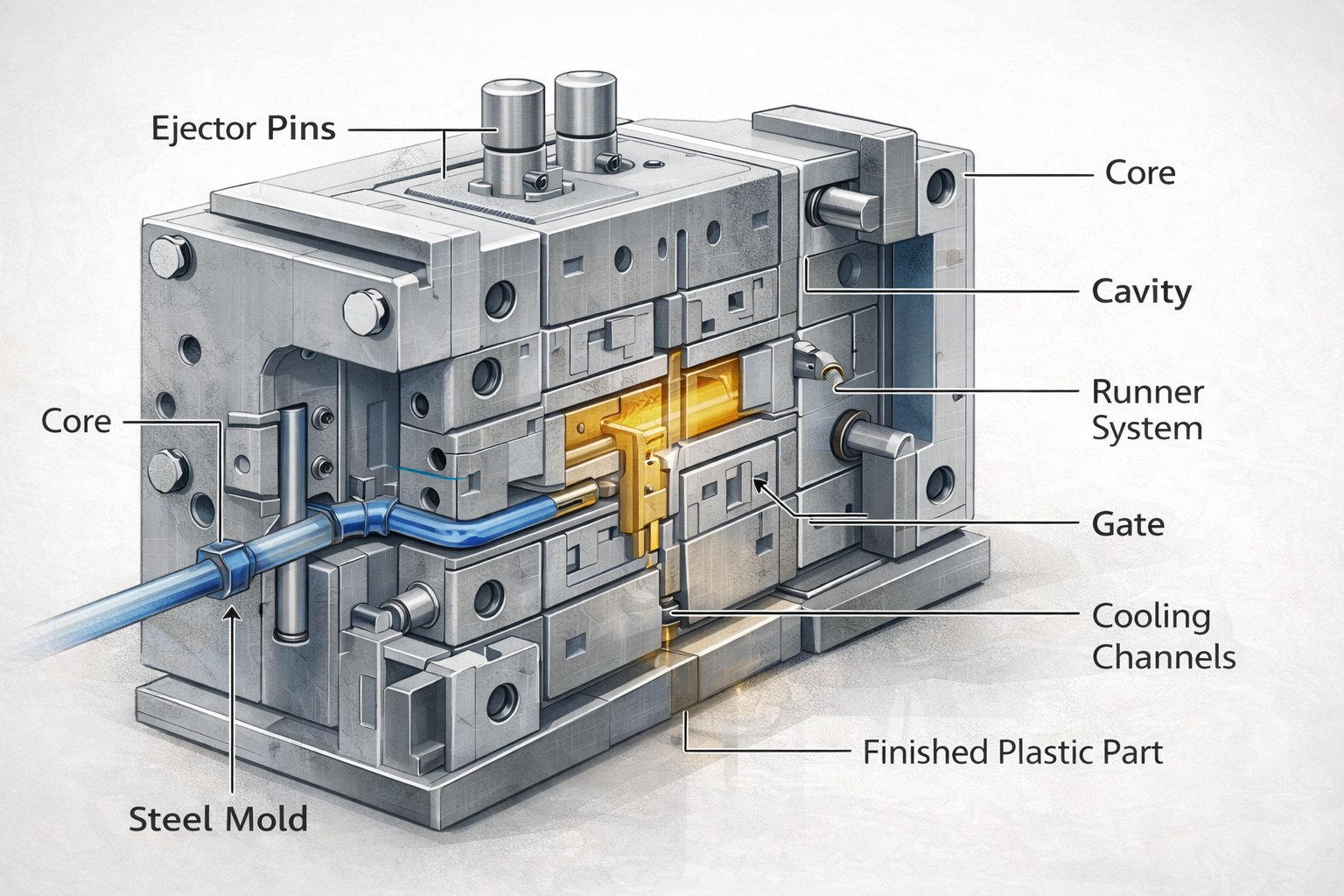
Before any material is cut, the tool design fixes where the part splits, how it fills, how it cools and how it ejects, and those four decisions determine the part’s quality.
The parting line is the first decision. It sets where the two halves of the tool meet, which determines the visible seam on the part, the placement of any side actions, and whether the geometry can be ejected at all. Moving a parting line after the tool is cut is expensive; agreeing it at design review is nearly free.
Gating follows. The gate position decides how material enters the cavity, which controls flow, weld line location and shrinkage patterns. A gate placed for easy tooling rather than for even filling produces parts with warpage or cosmetic defects that look like material problems but are process decisions.
Cooling and ejection complete the set. Cooling channels shape the temperature gradient, which drives cycle time and dimensional variation. Ejection determines how the part leaves the mold, and it affects where ejector marks appear. In a rapid tool, cooling is often simplified to reduce build time, which changes cycle time and slightly changes the shrinkage pattern, and that difference should be understood before the sampling parts are treated as production-representative.
The design rules that govern those decisions, including wall thickness, draft and rib guidance, are collected in the injection molding design tips.
How many cavities should a rapid tool have?
One, unless the sampling plan says otherwise.
A single cavity answers the validation questions at the lowest cost, and additional cavities are justified only when the sampling quantity or a multi-cavity balance issue requires them.
Multi-cavity tools cost more, take longer to build and introduce balance questions: material has to fill every cavity evenly, and small differences in gate or cooling geometry produce dimensional variation between cavities. On a production tool those differences are investigated and controlled because the tool will run for years. On a rapid tool, they add cost and complexity to a validation exercise.
There are two legitimate reasons to specify more than one cavity. The first is quantity: where the bridge parts themselves are needed in volume, a multi-cavity tool reduces the number of cycles required. The second is validation: where the production tool will be multi-cavity and the program needs to understand cavity-to-cavity variation early, a two-cavity tool can reveal it.
Where neither applies, a single cavity with a well-designed feed system is the efficient choice. It produces the parts needed for validation and keeps the tool simple enough to be modified if the sampling reveals a design change.
| Deliverable | Purpose | What it does not cover |
|---|---|---|
| Sampling parts in production material | Validate appearance, fit and function | Tool life and long-run repeatability |
| Process window | Establish the settings a production tool would use | Cycle time of a different cooling design |
| Dimensional report | Confirm the part meets its interfaces | Capability across a production run |
| Bridge quantity | Supply parts while production tooling is made | Cost parity with a production tool |
| Change record | Feed the production tool design | Changes that need a new cavity form |
What should sampling deliver?
Parts, data and a decision.
A sampling run should produce parts in the production material, dimensional results on the interfaces that matter, the process settings used, and a documented decision about the tool’s readiness.
The parts are the visible output, and they should be produced under conditions close to those a production tool would use, which means the material grade and the mold temperature profile are part of the plan rather than left to convenience. Where a substitute material is used because the production grade is not yet available, that substitution changes what the sampling can prove, and it should be recorded.
The data is the second output. Dimensional results on the interfaces, an assessment of appearance against the agreed standard, and a note of any defects with their cause. Where a defect is process-related, such as a weld line in an unavoidable location, recording it now prevents the same discussion at production sampling.
The decision is the third and most important output. Either the design is released for production tooling, or specific changes are agreed and the tool is adjusted. A sampling run that ends without that decision leaves the program in the position of having paid for the tool and learned nothing that changes the plan.
What materials and construction are used?
Aluminium and softer steels, built for speed of delivery.
Rapid tools are commonly cut from aluminium or pre-hardened steel, which machine quickly and can still produce a defined quantity of parts in the production material.
Aluminium is the standard choice for fast delivery. It machines quickly, transfers heat well, which shortens cycle time, and is inexpensive for a single cavity. Its limitations are wear at the gate and on the parting line, and lower stiffness under high clamping pressure, both of which limit the quantity it can produce and, in some geometries, the dimensional consistency across a run.
Pre-hardened steels offer more wear resistance and hold tolerance better over a longer run, at the cost of longer machining time. Where the part requires abrasive or glass-filled material, or where the bridge quantity is substantial, the steel option is usually worth the additional lead time.
Inserts and hybrids are a common middle path. A steel gate insert, a hardened core pin or a steel shut-off in an aluminium frame addresses the wear points without building a complete steel tool. That approach is also useful where a specific feature drives the tool life and the rest of the tool does not.
Mold steel grades and their selection criteria are compared in the existing 6CProto article on mold steel selection, and the materials context is published by bodies such as ASM International and the standards work of ASTM committee D20 on plastics.
Which quality gates belong in the mold build?
Design review, dimensional check, sampling and approval.
Four gates keep a rapid tool on schedule: the tool design review, dimensional verification of the cavity and core, the sampling run, and formal approval of the parts.
The design review happens before machining and covers the parting line, gating, cooling, ejection and any side actions. It is the last cheap moment to change a decision, because everything after it involves cutting material.
Dimensional verification of the cavity and core confirms that the tool matches the design intent before it is assembled and mounted. Checking at this point catches machining errors while the component can still be reworked, rather than after a sampling run produces parts that cannot be explained.
The sampling run then produces parts, and the approval gate closes the loop: the parts are measured against the interfaces, appearance is judged against the agreed standard, and the decision to release or adjust is documented. Where a program then moves to a production tool, the sampling report becomes the reference for what the production tool has to achieve.
6CProto reviews mold designs before manufacture and provides quality inspection reports on request, with a dedicated project manager following the program, so those gates are scheduled into the plan rather than added afterwards. The measurement methods used to verify molded parts are covered by the standards work of ASTM committee E28 on mechanical testing, and where a program involves coating or surface treatment, the relevant test framework is published by ASTM committee B08.
What drives the cost, and where can it be reduced?
Construction, cavity count and complexity.
Price is driven by the material of the tool, the number of cavities, the complexity of the parting line and the amount of side action the geometry requires.
The tool material sets a baseline. Aluminium machines faster and costs less; a steel tool takes longer and costs more but produces more parts. Cavity count multiplies the machining work, which is why a single cavity is the economical choice unless quantity requires otherwise.
Geometry is the largest variable. A part with a simple parting line needs a straightforward tool. A part with undercuts requires side actions, lifters or a more complex ejection system, and each of those adds components, machining and assembly time. That is why the same part designed with an undercut and without one can differ substantially in tooling cost, and why the design review is the point at which savings are found.
Three changes reduce cost without reducing what the tool can prove. Simplifying the parting line, relaxing an undercut that does not need to exist, and using a steel insert at the wear points instead of building the whole tool in steel. Each of those decisions is a design change rather than a purchasing one, which is why the tooling review is worth doing properly.
How does the program move to production tooling?
With the sampling data as the specification.
The transition is a handover of information: what the production tool must achieve, what the sampling established, and which changes were agreed.
The first item is the production specification. The sampling run established the process window, the parts that the tool produced, and the features that were difficult. Those findings tell the production tool designer where to add cooling, how to gate, and which tolerances need attention.
The second item is the change record. Any feature adjusted during sampling is documented, so the production tool is built with the change included rather than rediscovered. Where the change was made by modifying the tool, the modified geometry is the reference; where it was made in the CAD model, the model is the reference.
The third item is the acceptance criteria. Measurement methods, appearance standards and the interfaces that will be checked should carry from the sampling report into the production tool’s first article inspection. That continuity is what makes the two tools comparable and prevents the program from renegotiating what acceptable means.
The bridge function then continues in parallel. Where the rapid tool is producing usable parts, it can supply the program while the production tool is cut, which removes schedule pressure from the tooling decision and is often the strongest argument for building a bridge tool in the first place. The wider relationship between rapid tooling and production tooling is discussed in the 6CProto article on bridging prototype molds to mass production, and the manufacturing quality framework behind that transition is described by NIST MEP.
Running a rapid tooling program
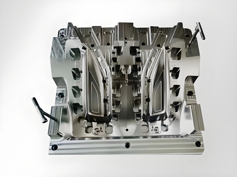
A rapid tooling program is a validation exercise with a manufacturing output. Its value comes from answering specific questions before a larger investment: can the geometry be molded, does the material behave, does the part assemble, and does the process window transfer. When those questions are answered and documented, the production tool starts from a known position rather than a hope.
The practices that make it work are unglamorous. Agree the parting line and gate position before cutting. Sample in the production material. Measure the interfaces and record the settings. Decide, in writing, whether the design is released. Those four steps are what separate a rapid tool that saved a program money from one that merely postponed a problem.
FAQ
What is meant by rapid tooling?
It describes molds built quickly and at lower cost than production tooling, usually from aluminium or pre-hardened steel, so that parts can be molded in the production material while a design is validated or a production tool is being made. The term covers a range of constructions, from a simple single-cavity tool to a more durable version intended to run a bridge quantity. What defines it is purpose rather than a specific material.
How is rapid tooling different from a prototype mold?
Mainly by intent and by what it has to prove. A prototype mold is often used for a small number of form-and-fit parts and may run a substitute material. A rapid tool is built to sample in the production material, to establish a process window, and frequently to supply parts while production tooling is manufactured. The construction can look similar; the specification and the acceptance criteria differ.
How many parts can a rapid tool produce?
It depends on the tool material, the part geometry and the material being molded. Abrasive or glass-filled resins wear gates and shut-offs faster, and thin steel sections or long cores are more sensitive to wear than solid blocks. Rather than relying on a general figure, state the quantity the tool has to produce and let the construction be selected around it, including steel inserts at the wear points where they matter.
Can a rapid tool be modified after sampling?
Yes, and that is one of its advantages. Aluminium and pre-hardened steel can both be welded and re-machined, and inserts can be replaced. The economical approach is to anticipate which features are most likely to change and design those areas as replaceable inserts. Where the change affects the cavity form itself, the alteration is still usually faster and cheaper than cutting a new production tool.
If a design needs molded parts before a production tool is justified, send the model with the interfaces that must be checked and the quantity you expect to run. 6CProto reviews mold design before manufacture, plans sampling against agreed criteria, and returns a DFM report with the quote. Upload the file at the 6CProto quote page or send it to projects@6cproto.com.