

A prototype that has been printed, cast and assembled can still fail the moment it is molded, because molding introduces variables the other routes do not have: melt flow, gate position, shrinkage and ejection. Prototype injection molding exists to expose those variables before a production tool is committed. The parts are real molded parts in the intended material, produced from a tool built for validation rather than for life. This guide covers what a prototype molding run should prove, how to specify it so the results transfer to production, what documentation it should leave behind, and how to turn the findings into controlled design changes.
What should prototype molding validate?
The design, the material and the assembly, together.
A prototype molding run should confirm that the geometry fills and ejects, that the chosen resin produces the required appearance and behaviour, and that the parts assemble with everything they meet.
Those three questions are connected. A part that fills correctly but warps will fail to assemble; a part that assembles but shows a weld line in a visible location fails the appearance requirement; a part molded in a substitute material may pass both tests and still behave differently in service. Validating them separately produces results that do not add up to a manufacturable product.
The prototype tool itself is built to answer those questions rather than to run for years. That means a simpler cooling layout, a lower cavity count and faster machining, all of which trade cost and delivery time against representativeness. Understanding where the trade applies is what keeps the results useful: a part produced with a simplified cooling circuit may measure slightly differently from the eventual production part, and that difference should be anticipated rather than treated as a defect.
What the run cannot prove is production economics. Cycle time, tool life and long-run repeatability belong to the production tool, and the prototype’s role is to make sure that tool is built around a design that already works.
Why does molding in the production material matter?
The resin drives appearance, shrinkage and behaviour.
A prototype molded in a substitute resin validates geometry but not shrinkage, surface finish or mechanical behaviour, so the results transfer to production only partially.
Each polymer family shrinks differently as it cools, and the filler content changes both shrinkage and surface appearance. A part designed and validated in an unfilled general-purpose resin will not produce the same dimensions when molded in a glass-filled engineering grade, and the difference is often large enough to affect fits. Surface finish behaves similarly: some resins reproduce a polished cavity faithfully, others show flow marks or a duller finish that a different grade would not.
Mechanical behaviour is the third consideration. Impact resistance, stiffness and heat tolerance are properties of the specific grade, and a prototype in a substitute material cannot validate a load case or a temperature requirement. Where the production grade is genuinely unavailable at prototype stage, that limitation should be recorded, and the design review should treat the affected requirements as unproven rather than passed.
Where the production resin is available, molding the prototype in it is the single change that makes the most difference to how much the run proves. The specifications behind those choices are published by standards bodies such as ASTM committee D20 on plastics, and the materials engineering context by ASM International.
How do draft, wall thickness and gate location affect trial parts?
They decide whether the tool can run the design at all.
Draft allows the part to release, wall thickness governs flow and cooling, and gate location controls how the cavity fills, which is where weld lines and warpage originate.
Draft is the most common source of prototype rework. A vertical wall with no draft creates friction as the part is ejected, which leads to scuffing, drag marks or a part that sticks. The amount of draft needed depends on the surface finish of the cavity and the depth of the feature, and shallow features tolerate less than deep ones. Adding draft after the tool is cut means re-machining the cavity, so it belongs in the design review.
Wall thickness behaves as it does in production. Sections that are too thin may not fill completely, producing short shots at the end of the flow path. Sections that are too thick cool slowly, which increases cycle time and produces sink marks on the opposite face. Nominal sections that are too far from uniform create the differential shrinkage that warps a part after ejection.
Gate location then decides how the melt enters. The gate sets where the flow front travels, where two fronts meet, and therefore where a weld line will appear. It also influences shrinkage direction, because material shrinks along the flow path differently from across it. On a prototype tool the gate is often simplified for machining, which changes those effects; the design rules behind the choices are collected in the injection molding design tips.
| Question | Prototype production tool | Limitation |
|---|---|---|
| Does the geometry fill? | Yes | Gate direction may differ from production |
| Does the part eject cleanly? | Yes, with draft in place | Simplified ejection may need revisiting |
| Are dimensions correct? | Yes, within tool and material capability | Simplified cooling changes shrinkage slightly |
| Is the appearance acceptable? | Yes, in the production resin | Cavity polish may differ from production |
| Does it assemble? | Yes, with real hardware | None, provided the quantity is adequate |
| Is cycle time economical? | Indicative only | Production cooling is optimised differently |
| Will the tool last? | Not applicable | Tool life belongs to the production tool |
How many parts should a prototype run include?
Enough to assemble, test to failure and keep a reference.
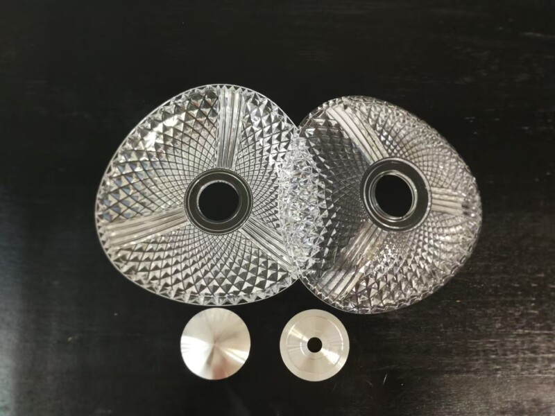
A prototype run should produce enough parts to build the assembly, to test it, and to retain an approved reference part for later comparison.
The quantity follows from the validation plan rather than from a standard figure. Testing an assembly may consume several sets, particularly where a test is destructive. Functional testing, such as cycling a latch or a hinge, consumes parts as well. And a reference set needs to be kept in the condition it was approved, so that later batches can be compared against something physical rather than a description.
Two additional groups are often worth including. First-article samples measured and documented, which become the dimensional reference. And some spare parts, because the most common problem with a prototype run is running out of parts before the testing is complete.
Where the quantity is defined before the tool is quoted, the tool can be designed around it. A run of twenty parts and a run of two hundred imply different tool constructions and different levels of wear resistance at the gate, and the difference in cost is usually small compared with the cost of a second run.
How do trial findings become controlled changes?
Record, assess, then decide.
Each finding from a trial run should be recorded with its cause, assessed for its effect on the design and the tool, and resolved by a documented decision rather than by an informal adjustment.
The record matters because findings arrive in different forms. A dimensional deviation has a measurement and a cause, often shrinkage or cooling. A cosmetic defect has a location and a process explanation, such as a weld line where two flow fronts met. An assembly problem has a specific interference or clearance. Writing those down turns a set of impressions into a list that can be worked through.
Assessment then sorts them. Some findings require a design change, which flows back into the CAD model. Some require a tool change, such as adjusting a gate or adding draft. Some are process adjustments that will be carried into the production tool’s settings. And some are accepted as inherent to the design, in which case the acceptance criteria should be updated to reflect reality.
The decision is what closes the loop. Recording an issue without deciding how it will be resolved leaves the same question open at production sampling, when the answer is more expensive. A short review with the tooling engineer, the designer and the quality representative resolves most trial findings in a single sitting.
What documentation should a prototype build leave behind?
Dimensional results, settings and an approved reference.
A prototype build should produce a dimensional report on the interfaces, the process settings used, and an approved reference part, all tied to a specific design revision.
The dimensional report should concentrate on the features that decide assembly. Reporting every dimension produces a document nobody reads; reporting the interfaces, the critical clearances and the features that failed earlier iterations produces one that is used. The method should be recorded alongside the numbers, so the results can be reproduced.
The process settings matter because they transfer. Melt temperature, mold temperature, injection profile and cooling time established on the prototype tool are the starting point for the production tool’s sampling, and having them recorded shortens that process considerably.
The approved reference part closes the set. Where a program runs multiple iterations, the final approved part from the last iteration is the physical standard that later batches are compared against, and it is what makes an appearance or fit assessment possible months later. 6CProto provides quality inspection reports on request and follows each program with a dedicated project manager, so the documentation scope can be agreed before the tool is built. The measurement methods that support those reports are defined by ASTM committee E28 on mechanical testing, and where a part is coated or finished afterwards, the relevant test framework is published by ASTM committee B08.
What drives prototype molding cost and lead time?
Tool complexity, cavity count and iteration count.
Price depends on how complex the tool is, how many cavities it has, and how many times the design is revised before the production tool is committed.
Tool complexity is the largest driver. A part with a simple parting line and no side action needs a straightforward tool. A part with undercuts requires lifters or side actions, and each adds components, machining and assembly. Reducing an unnecessary undercut is the single most effective cost reduction on a prototype tool.
Cavity count is the second. A single cavity produces the validation parts at the lowest cost; additional cavities are justified only where the quantity is large or where production will be multi-cavity and the program needs to understand cavity variation early.
Iteration count is the third and the one most under a program’s control. Each revision costs a tool modification or a new insert plus another sampling run. Resolving design questions in the CAD review, before the tool is cut, is considerably cheaper than resolving them in molded parts, which is why the DFM review is worth taking seriously on a prototype program. Requests submitted through the quote flow receive that review before production starts.
Running a prototype molding program
Prototype injection molding is a validation exercise that produces real parts. Its value depends on three decisions: molding in the production resin, defining what the run must prove before the tool is quoted, and documenting the results against a specific design revision so the production tool starts from evidence.
The programs that go well share a pattern. They resolve draft, wall thickness and gate questions in the design review. They produce enough parts to test and to keep a reference set. They record settings and dimensions. And they decide what to change before committing to production tooling, rather than carrying open questions into the next stage. The materials specification context behind those decisions is published by ASTM committee D20, and the quality practices by NIST MEP.
FAQ
What is the difference between prototype molding and production molding?
The tool, and the purpose it serves. A prototype tool is built quickly and simply to produce parts for validation, usually in a single cavity with simplified cooling. A production tool is built for the product’s life, with optimised cooling, a higher cavity count and materials selected for wear. The parts from a prototype run can be representative if the production resin is used, but the production economics come only from the production tool.
How long does prototype injection molding take?
Lead time depends on the tool’s complexity rather than on the quantity of parts. A single-cavity tool with a straightforward parting line and no side action can be designed, machined and sampled considerably faster than one with lifters or a complex shut-off. Building the sampling window into the plan, rather than treating it as an extra, is what keeps the schedule realistic.
Can prototype parts be used in the final product?
They can be, if they are molded in the production material and approved against the same criteria the production part will meet. Many programs ship prototype-molded parts in early production units, and the practice is standard where the design is settled before the production tool is ready. What must be managed is the difference between the two tools, which is why a documented dimensional report is worth having.
What are the main risks in a prototype molding program?
Three recur. Using a substitute resin, which invalidates any conclusion about shrinkage, appearance or mechanical behaviour. Cutting the tool before the design questions are resolved, which turns cheap CAD changes into expensive tool changes. And failing to document the run, which leaves the production tool starting from scratch rather than from evidence. Each is avoidable with a review before the tool is built.
If a design is ready for molded validation parts, send the model with the interfaces that must be checked and the resin you intend to produce in. 6CProto reviews the design before tooling, molds prototype runs in the production material, and returns a DFM report with the quote so the sampling plan is agreed in advance. Upload the file at the 6CProto quote page or send it to projects@6cproto.com.