

A metal additive part that arrives distorted, with supports fused into a sealing face, is not a process failure: it is the predictable result of a build that was orientated before anyone decided which faces mattered. Laser powder bed fusion is now a production route for impellers, manifolds, heat exchangers, brackets and tooling inserts, and the parts that come out usable share a specification pattern. This guide covers what a metal AM part can hold, how alloy choice and build orientation decide distortion, what post-processing is required rather than optional, and how to specify inspection and traceability for a part that carries load.
What can a metal AM part hold in tolerance?
Tight on machined faces, looser as-built.
Laser powder bed fusion produces a near-net shape; features that must be exact are machined afterwards, while as-built surfaces carry both a rough texture and distortion from thermal cycling.
Two effects set the as-built accuracy of a metal part. The first is the surface: partially melted powder adheres to downward-facing and vertical surfaces, producing a rougher finish than the same material machined. The second is thermal distortion, because each laser pass deposits heat into material that is already cooling, and residual stress accumulates until the part is cut from the plate.
The practical specification response is to divide the drawing. Interfaces that locate, seal, bear or transmit load are designated as machined surfaces with a callout and an allowance. Cosmetic and internal surfaces keep a general tolerance, and the near-net shape leaves enough material for the machining operation to reach nominal. This is why metal AM parts are usually quoted in two steps: printing and then finishing.
Where a program needs the achievable range for a specific feature, the answer depends on material, geometry and orientation rather than on the machine alone. 6CProto’s tolerance framework sets out how those callouts are handled, and confirming them before the drawing is released is faster than discovering them at first article.
What do SLM and DMLS actually mean?
Two names for laser powder bed fusion.
Both melt successive layers of metal powder with a laser, and the practical question is which alloy and parameters a supplier runs.
Selective laser melting describes the process by what it does to the powder: particles are fully melted and fused into a dense part. Direct metal laser sintering describes the same family of machines from the perspective of consolidating powder without a separate binder. In current industrial practice, the distinction between the two labels is smaller than the difference between one supplier’s parameters and another’s, which is the information that actually affects your part.
What matters on a purchase order is therefore specific: the alloy and its powder specification, the layer thickness the part will be built at, the orientation, the support strategy, the heat treatment, and which faces will be machined. Those six items determine the result far more than the acronym used to describe the machine. The process family itself, and the terminology around it, is defined in the standards work coordinated through ASTM committee F42, and the engineering context for the process is summarised in the ASME additive manufacturing topic page.
How should the alloy be chosen?
By service environment, then by availability.
Aluminium suits lightweight structures, stainless covers corrosion, titanium balances strength and weight, and nickel alloys handle heat.
Alloy selection for metal AM starts with the same questions as any other metal part: temperature, load, corrosion environment, weight budget and any regulatory requirement. The difference is that not every alloy prints with equal reliability, and the powder specification matters as much as the alloy designation. Spherical, gas-atomised powder with a controlled particle-size distribution flows and melts predictably; recycled powder changes with each build cycle, which is why a supplier’s powder management practice is part of the qualification rather than a housekeeping detail.
The materials most often specified for laser powder bed fusion are aluminium alloys for lightweight brackets and housings, stainless steels including 316L for corrosion resistance and general engineering, titanium alloys where strength-to-weight matters, and nickel superalloys such as Inconel 718 for high-temperature service. 6CProto documents the grades it runs on the titanium TC4, stainless steel 316L and Inconel 718 material pages.
| Alloy family | Requirement it addresses | Typical metal AM parts |
|---|---|---|
| Aluminium alloys | Low weight with moderate strength | Brackets, housings, heat transfer bodies |
| Stainless steel 316L | Corrosion resistance, general engineering | Fluid components, manifolds, food and medical hardware |
| Titanium alloys | Strength-to-weight, biocompatibility | Aerospace brackets, medical implants and instruments |
| Nickel superalloys | High-temperature strength, oxidation resistance | Hot-section components, rocket and turbine parts |
| Tool steels | Wear resistance in tooling | Conformal-cooled mold inserts, die components |
How do orientation, supports and distortion interact?
Orientation decides both distortion and support scars.
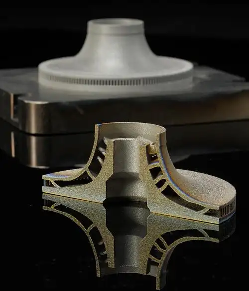
The build angle sets which faces need support, how heat accumulates in the part, and where residual stress will pull the geometry when it is cut free.
Support structures in metal printing serve two purposes: they hold overhanging geometry, and they conduct heat away from the melt pool so that the layer does not curl. Both functions mean supports are dense, and removing them is a machining and finishing operation rather than a simple snap-off. Every surface that touches a support carries witness marks, so support placement is a specification decision, not just a build decision.
Residual stress is the second effect of orientation. The laser heats and cools material in a moving pattern, and the part accumulates stress that is partly released when it is separated from the build plate. Parts built with large, flat, unsupported sections are the most likely to bow, which is why the same geometry built at an angle often holds shape better even though it requires more support.
The practical guidance is to designate the faces that must not carry support marks, accept that this constrains orientation, and let the DFM review return both the orientation and the support plan. Features that cannot avoid distortion should be left with machining allowance rather than specified as-built.
Which post-processing steps are required rather than optional?
Heat treatment, support removal, machining and finishing.
A metal AM part is not finished when it leaves the machine: stress relief, separation from the plate, support removal, interface machining and any surface finishing are part of the production route.
Heat treatment comes first in most routes and serves to relieve the residual stress that accumulates during the build. Without it, a part can distort later, either when it is cut from the plate or when it is machined. Depending on the alloy and application, a hot isostatic pressing step may also be specified to reduce internal porosity where fatigue performance matters.
Support removal and separation follow, and both are metal-cutting operations on a part that is often thin-walled and geometrically complex. Machining then brings the designated interfaces to their callouts, which is where the near-net shape becomes a functional component. Surface finishing completes the route: blasting for a uniform appearance, polishing or coating where the application requires it, and masking where the machined faces must stay bare.
Every one of those steps adds lead time and cost, and each should be specified rather than assumed. A quote that names the operations is easier to compare with another, and it prevents the situation where a part arrives with the geometry right and the interface unfinished.
What are the limits on minimum features and internal channels?
Internal channels justify metal AM and set its limits.
Internal passages that cannot be machined are routine in this process, while very small features, thin walls and unsupported surfaces depend on orientation and on what the powder can be cleared from.
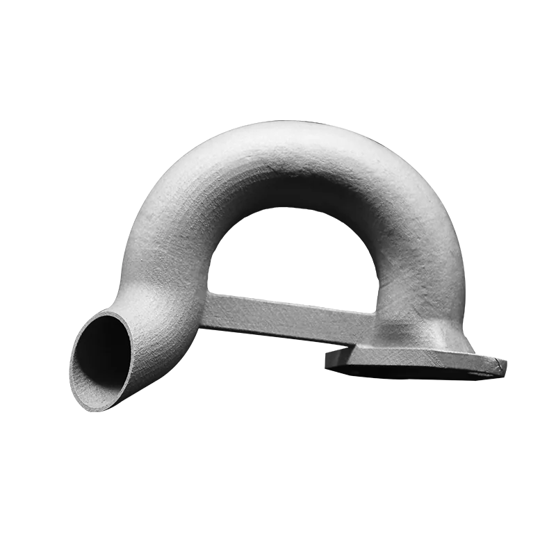
Internal channels are the strongest argument for the process. A conformal cooling channel that follows the contour of a mold insert, or a manifold with curved passages instead of drilled straight lines, can only be produced additively, and both are routine applications. The limits are practical rather than conceptual: a channel must be large enough that powder can be removed after the build, and its shape must allow support where the geometry overhangs.
Minimum features behave like other powder-bed processes. Walls need enough thickness to survive handling and machining, fine details round off at the melt-pool scale, and small holes that carry a tolerance are usually drilled afterwards. Where a feature sits close to the limit, the useful question is not whether it can be printed but whether it can be inspected and finished, since both follow the build.
Powder removal deserves specific attention on complex internal geometry, because trapped powder inside a finished part is difficult to detect and expensive to correct. Escape paths belong on the model, and the review should confirm them before the build is scheduled.
How should inspection and traceability be specified?
Against the interfaces, with the build record attached.
Dimensional inspection covers the machined interfaces, material documentation confirms the powder, and the build record ties the part to its parameters, orientation and heat treatment.
Three levels of evidence are worth asking for on a metal part. At material level, the powder specification and its condition establish what was built. At process level, the build parameters, orientation, heat treatment and any pressing step describe how it was made. At part level, dimensional results on the machined interfaces and any non-destructive examination confirm the outcome. That structure mirrors the way the measurement methods used across additive processes are described in the NIST additive manufacturing program.
The requirement should be proportional to the application. A bracket for a fixture needs dimensional verification on its interfaces; a part for a regulated industry may need documented material traceability, mechanical test data and, in the case of medical devices, an evaluation that considers material, process and cleaning together, as set out in the FDA guidance on technical considerations for additive manufactured medical devices. Where independent verification is required rather than an internal record, certification bodies such as UL publish their additive manufacturing service scope. 6CProto provides quality inspection reports on request and assigns a project manager to each order so the reporting scope can be agreed at review stage.
What drives the cost of a metal AM part?
Build time, support volume, alloy, and post-processing.
Machine time scales with part height and volume of support, exotic alloys cost more per kilogram, and the finishing route, including machining and heat treatment, is priced separately.
Build time is the first driver, and it is influenced by part height, by the area of each layer, and by the layer thickness the geometry requires. A part that occupies less build height costs less machine time, and a design that reduces support volume reduces both material and removal labour.
Alloy choice is the second. Titanium and nickel powders cost considerably more per kilogram than stainless, and their machining behaviour adds time to any finishing operation. Where a material substitution is possible without compromising the application, it is worth testing before assuming the expensive grade is required.
Post-processing is the third and the most variable. Heat treatment, pressing, support removal, interface machining, blasting and inspection are each separate operations, and a quote that bundles them hides the comparison. Asking for the operations to be listed is the fastest way to understand where the cost sits and where a design change would help.
Specifying a metal AM part that works
Metal additive manufacturing is at its best when the geometry cannot be made any other way, and at its worst when it is used to produce a simple shape that a machining centre would hold more accurately for less money. The parts that succeed are the ones specified for the process: internal channels that follow a thermal path, consolidated assemblies that remove joints, and lightweight structures that would otherwise be machined from a large billet with most of the material removed as chips.
On those parts, the specification decisions are consistent. Interfaces are machined rather than printed. Orientation is chosen to protect critical faces and to manage distortion. Heat treatment and support removal are planned as production steps, not discovered as extras. Inspection covers the interfaces with the build record attached. Where those four items are in place, laser powder bed fusion behaves like a production process rather than an experiment.
FAQ
How much does it cost to 3D print metal?
Price follows machine time, support volume, alloy and post-processing rather than material weight alone. A part that occupies less build height, needs fewer supports and avoids an exotic alloy costs less, and the finishing operations, from heat treatment to interface machining, are priced separately. Ask for the operations to be listed in the quote: that is the quickest way to see where the cost sits and which design change would reduce it.
Is metal 3D printing only for prototypes?
No. Laser powder bed fusion produces end-use parts in applications where the geometry cannot be machined conventionally, including conformal-cooled tooling inserts, consolidated fluid manifolds, lightweight brackets and heat exchangers. What determines suitability is not the volume but the geometry and the qualification route: a part with internal channels and a defined inspection plan is a production candidate, while a simple block is usually better machined.
Why do metal AM parts need heat treatment?
Because the build process leaves residual stress. The laser deposits heat into material that is already cooling, and the accumulated stress can distort the part when it is separated from the build plate or when it is machined afterwards. Stress relief is therefore a production step rather than a refinement. Depending on the alloy and the fatigue requirements, a hot isostatic pressing step may be added to reduce internal porosity.
Can internal channels be printed reliably?
They are one of the main reasons to use the process, and they are routine when the geometry allows powder to be removed afterwards and the overhanging sections can be supported. The design questions are channel size, escape paths and how the channel will be inspected. Where a channel must carry fluid or pressure, its internal surface condition matters as much as its shape, so specify the requirement rather than leaving it to the build.
If a metal part has geometry that conventional machining cannot reach, send the model with the faces that must remain exact. 6CProto reviews metal AM parts for manufacturability, runs printing alongside heat treatment, machining and finishing, and returns a DFM report with the quote. Upload the file at the 6CProto quote page or send it to projects@6cproto.com.