

“Anodizing” covers two very different engineering choices. Type II (standard or decorative anodizing) is the finish most people picture on consumer aluminum: a thin, uniform oxide layer that can be dyed in a wide color range. Type III (hard anodizing or hard coat) is a thicker, denser oxide layer built for wear resistance and harsher service. Both are sulfuric acid anodizing processes on aluminum, but the bath conditions and the coating thickness differ enough that the two should be specified for different reasons, not treated as interchangeable.
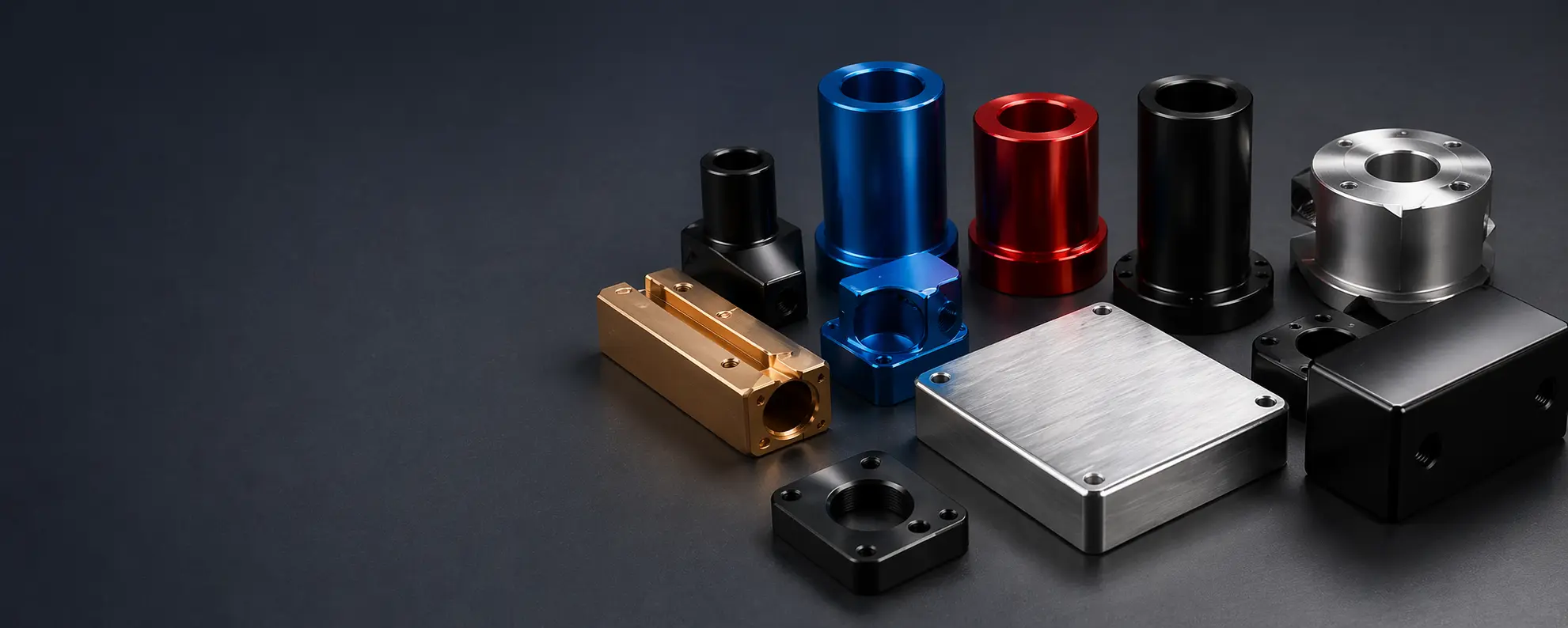
What Changes Between Type II and Type III
In both processes, the part becomes the anode in an acid bath, and the surface converts to an aluminum oxide layer. Type III uses lower bath temperature, higher current density, and more agitation, which produces a thicker and denser coating than Type II. A common shorthand is thickness: Type II decorative coatings typically run in the range of about 5–25 µm, while Type III hard coatings commonly run from about 25 µm upward, with process-specific practical limits. Those numbers are starting points; the achievable thickness depends on alloy, geometry, and the anodizer’s process.
The alloy matters more than most drawings acknowledge. Pure aluminum and 5xxx and 6xxx alloys anodize cleanly and evenly; heavily alloyed or high-copper casting alloys can produce duller, less consistent coatings and may need special process approval. If the drawing does not state the alloy and temper, an anodizer cannot honestly promise a finish class.
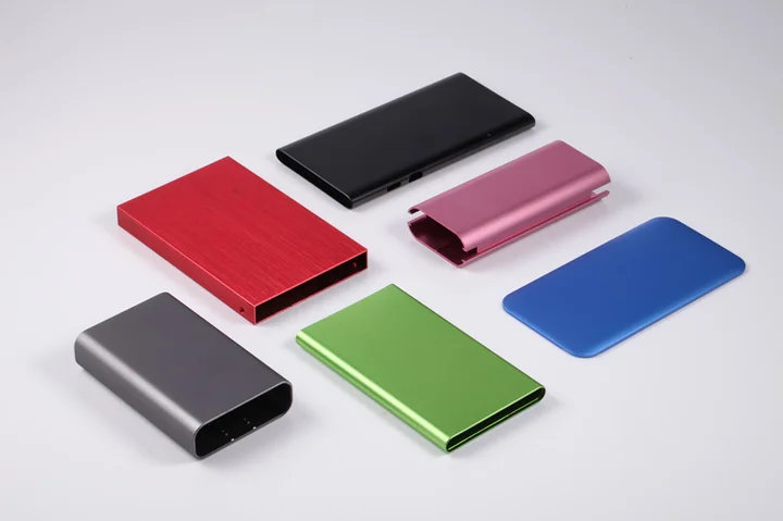
Thickness, Hardness, and Wear Differences
The practical difference is mechanical. A standard Type II coating is thin and primarily protects against corrosion and mild handling; it will not survive repeated sliding contact. A Type III hard coating is substantially thicker and harder, which is why it shows up on components that slide, clamp, index, or wear: pistons and cylinders, fixture details, valve bodies, bearing surfaces, and parts that are assembled and disassembled repeatedly.
Harder is not always better. A very hard, thick oxide on a thin aluminum wall can reduce the part’s fatigue tolerance under heavy cyclic load, and coating thickness on edges and sharp corners behaves differently from coating on flat faces. If the application is truly wear-critical, verify the coating with the anodizer on the actual alloy and geometry rather than assuming a generic hardness value.
Dimensional Growth and Tolerance Planning
Anodic coatings grow from the surface, and part dimensions change by a meaningful fraction of the coating thickness. The oxide builds both inward and outward, so a tight bore, a threaded hole, or a press-fit surface specified before anodizing will not be the same size after coating. Standard practice is to plan the allowance before machining or to mask, plug, or re-machine the critical features after coating.
Threads deserve special attention. Internal threads that must accept a standard screw are usually masked or plugged because the coating changes the pitch diameter fit. If a threaded feature must remain coated, the drawing should state the pre-coat thread size and the class required after coating so the shop can cut the thread with allowance in mind.
Tolerances should be allocated to the right side of the process. Instead of writing a tight final dimension with no coating note, state the dimension after anodizing, the coating thickness range, and which surfaces are masked. That set of information lets the machinist and anodizer split the tolerance realistically.
Color, Sealing, and Cosmetic Expectations
Type II is the choice when color is the priority. Clear, black, and a broad dye palette are available, and decorative parts are usually sealed after dyeing to improve corrosion resistance and color stability. Type III hard coat has a narrower appearance range; it is often darker, from gray to dark bronze or black depending on alloy and process, and matching a specific color across batches is harder than with Type II.
Sealing deserves a callout of its own. Sealing closes the porous oxide layer and improves corrosion resistance, but it can shift color and, on hard coat, change the surface behavior that the wear application depends on. When both corrosion and wear matter, specify the coating thickness, the sealing step, and the acceptance test together.
For visible surfaces, agree on an acceptance sample rather than a written description alone. Anodized color and texture vary with alloy, racking position, and batch, and “clear anodized” means different things to different shops. A signed sample or reference plate removes most of the argument later.
Drawing Callouts for Hard Coat on Machined Parts
A useful finish callout tells the shop what to do and what to leave alone:
- Process and thickness range. Example: “Type III hard anodize, coating thickness 0.0015–0.002 in, per the project specification” — and if a military standard such as MIL-A-8625 is named, cite the edition the program actually uses, because the applicable revision must be confirmed with the customer and the finisher. If the project does not use a military or internal standard, state the thickness in µm and the required test method.
- Masking. List the threads, bores, datum surfaces, or mating faces that must remain uncoated.
- Dimension basis. State whether critical dimensions are measured before coating or after coating.
- Acceptance. Specify the sample, the color/texture reference, and any corrosion or wear test that applies.
- Alloy confirmation. Ensure the material callout and the anodizing callout are on the same drawing.
Selecting the right coating in practice
A part-by-part example shows the decision in action. A machined aluminum component family includes a wear plate that slides against a mating part, a cosmetic housing that is visible on the product, and a threaded fitting that carries a seal. The wear plate specifies Type III hard coat because the sliding surface needs the thickness and the wear resistance, and the drawing carries the coating thickness and the surface that is masked from the coating where the fit is tight. The cosmetic housing specifies Type II with a dyed color and a sealed surface, because the appearance is the requirement and the coating thickness is planned only on the visible faces. The threaded fitting is the hardest call: the threads are masked so the screw fits after coating, and the sealing face is hard-coated with the thickness planned before machining. Three parts, three anodizing decisions, and each one is made from the function — the wear, the appearance, and the fit — rather than from a single “anodize” note. The example is the anodizing specification in miniature: the coating is chosen for what the part does, and the drawing carries the thickness, the masking, and the measurement basis that make the choice enforceable.
The example also shows where the process review catches the mistakes. A Type III callout on a thin-walled housing that needs flexibility would be wrong for the service; a Type II callout on a sliding surface would wear through; and a callout without the masking note would let the coating close the threads. The review should ask what the coating is protecting and where the part will fail if the coating is wrong, and the answer sets the type, the thickness, and the masking. The anodizer should see the function with the drawing, because the anodizing decision is an engineering choice that the finisher can confirm but the designer must make. When the function drives the callout and the sample verifies the result, the anodized part performs as designed — and the finish that looked right on the sample is the finish that works in service. The Type II-versus-Type III decision is not a catalog choice; it is the coating expression of the part’s requirements.
The coating decision should also be verified on a sample before the production run, because the anodizing result is set by the alloy, the process, and the batch. The sample part is anodized with the production thickness and finish, measured for the coating and the fit, and checked against the appearance requirement; the sample becomes the acceptance reference that the production parts are compared against. When the sample reveals a problem — a color mismatch, a thickness variation, or a masked thread that was not protected — the fix is made before the production run, and the drawing and the process are corrected while the change is cheap. The anodizer should confirm the alloy and the process with the sample, and the first article should repeat the sample’s measurements before the lot is accepted. The verification discipline is what closes the loop between the Type II or Type III callout and the delivered part: the coating that was specified on the drawing is measured on the part, and the finish that the sample approved is the finish that the production parts carry.
The verification also protects the assembly and the service. The coating thickness is measured at the functional surfaces, the threads are checked with the mating hardware after coating, and the sealed or dyed finish is compared against the color standard under the agreed lighting. The records — the coating thickness, the masking check, and the appearance approval — travel with the part, and they are the evidence that the anodizing specification was met. When a coated part fails in service, the record shows whether the coating, the allowance, or the process was the cause, and the corrective action targets the real issue. The Type II-versus-Type III decision is complete when the callout is on the drawing, the sample is approved, and the production parts are verified against it — and the anodized component then performs as the design intended, with the evidence to prove it.
Because Type II and Type III are priced and quoted differently, sending a finish callout with the RFQ — not after the quote — is what makes quotes comparable. The 6CProto anodizing service team can review the drawing with the coating and masking notes before you commit to a process.