

Explore Quality, DFM & Procurement Guides
On a backlit translucent housing, the gate is not only where melt enters the cavity. It is where knit lines form, where blush or jetting can freeze into the optical face, and where shear heat can leave a permanent witness. Specifying gate design translucent injection molding for lighting means treating gate type and location as cosmetic decisions before steel is cut, not as a tooling detail the shop improvises after T1 fails the light box.
This page covers why the gate is a lit-face decision, how edge, submarine and fan gates behave under thin sections, which knit lines become visible when backlit, when replaceable gate inserts pay for themselves, and what belongs in the DFM review. Hub-level gate mentions in the mould-lever table stay there; deeper gate cosmetics for translucent thin walls live here. Programme context links to the bespoke pendant light case.
Why is the gate a cosmetic decision on a lit face?
Gate location sets shear, knit lines and vestiges.
Every gate leaves a freeze-off mark and a flow front history. On opaque parts those marks hide under paint or texture. On translucent lighting parts they become bright or dark bands once LEDs illuminate the wall from behind.
Designers who place a gate on the centre of a clear dome for “balanced fill” often discover a bullseye or blush that no polish cycle removes. Moving the gate to a hidden flange, rim or boss can add weld lines elsewhere; those welds must be steered off the primary lit zone or into textured regions. The cosmetic map and the gate map are the same drawing.
Hot-runner versus cold-runner choices change vestige size and thermal history at the gate. Hot-runner suppliers such as Mold-Masters and Husky document tip styles and thermal control; mould standard components from HASCO cover cold-runner inserts and tunnels. Machine capability context from ENGEL and ARBURG matters for thin-wall fill pressure, but it does not choose your gate face. 6CProto flags gate-to-optic conflicts during free DFM on plastic injection molding programmes.
How do edge, submarine and fan gates behave under thin sections?
Thin walls amplify shear and freeze-off marks at gates.
Edge gates are simple and common on flat panels, but on thin translucent faces they can leave a visible tab scar and directional flow lines radiating into the optic. Submarine (tunnel) gates hide the vestige under a parting line or on a non-show edge, at the cost of higher shear and potential blush if the tunnel is undersized for a stiff optical melt. Fan gates spread melt to reduce jetting into thin sections, yet they enlarge the land that must be trimmed and can still show a linear witness if the fan sits on a lit flange.
Gate thickness relative to wall thickness controls freeze-off and packing. An oversized gate on a thin clear wall can overpack and print residual stress; an undersized gate shears the melt and clouds the entry zone. Optical grades such as PC and PMMA react differently to that shear, which is why resin selection (covered in the optical-plastics article) and gate sizing must be reviewed together.
Industry polymer guidance from Plastics Europe and the Plastics Industry Association frames material families; it does not size your gate. Ask the toolmaker for a sketched gate land, tunnel diameter and expected vestige height on the quotation, not only a CAD with a pin-point arrow.
Which knit lines become visible when backlit?
Welds across lit zones glow or darken under LEDs.
Knit (weld) lines form wherever flow fronts meet. On translucent parts those interfaces scatter light. A knit that is barely visible in reflected room light can become a bright streak or a dark hairline once the LED board is powered. Multi-gate layouts that look balanced on opaque enclosures often create a star of welds on a clear diffuser.
Mitigation is geometric first: move meeting points into ribs behind the face, into textured bands, or into regions outside the primary beam. Process tweaks (melt temperature, speed) help only within a narrow band and can trade knit visibility for blush or flash. Simulation should report weld locations against the lit-face mask you care about, not only against a generic sink risk map.
When a knit cannot move, specify whether it is acceptable under the light-box standard and photograph the limit sample. Do not leave “no knit lines” as an unmeasurable wish on a multi-window clear part. Related warpage and residual-stress behaviour that also shows under backlight is discussed in 6CProto’s guide to injection molding warpage; this page stays on gate-driven cosmetics.
When do replaceable gate inserts pay for themselves?
High-shear clear resins wear gates; inserts cut steel risk.
Optical melts and filled clear grades can erode gate lands faster than commodity ABS. A worn gate changes vestige height, shear and fill balance mid-campaign, which shows up as a sudden rise in light-box rejects. Replaceable gate inserts let the shop restore the land without welding and re-polishing the entire cavity block.
Inserts cost more up front and add fit-up risk if poorly keyed. They pay when volumes are high, resins are abrasive or high-shear, or the gate sits on a cosmetic edge that cannot tolerate weld repair marks. The hub’s mould-lever table lists replaceable gates as a durability option; here the buyer question is whether your translucent lighting tool needs that option before T1, not after the land collapses.
Hard coatings and polished inserts extend life further. Coating choices interact with release and optical polish and should be named on the tool design review. Broader mould durability framing lives on the shop’s precise custom mould design guide — link it rather than restating that whole durability argument.
What belongs in the DFM review before steel is cut?
Map gates to lit zones, welds, vestiges and insert strategy.
A useful DFM for translucent lighting gates includes: proposed gate type and location on both cavity and part views; predicted weld lines versus the lit-face mask; expected vestige size and trim method; hot- versus cold-runner rationale; insert and coating notes; and the light-box method that will accept or reject gate cosmetics. Without those items, quotes compare steel tonnage, not optical risk.
Include resin grade and drying notes because gate shear depends on viscosity. Include texture callouts where welds will land. Ask whether first-article price covers one gate relocation iteration or whether relocation is a fully re-quoted steel change. Prototype routes through prototype injection molding can prove gate cosmetics on soft tools before production steel freezes the decision.
Measurement and documentation habits from NIST MEP apply to cosmetic FAIR photos as much as to caliper readings. Material producers such as Covestro publish processing windows that influence gate design inputs; they do not replace your weld map.
Valve-gate timing on multi-drop clear parts can stagger flow fronts to move knits, but only if the tool was built for sequential fill. Retrofitting sequence after T1 is rarely cheap. If the appearance map shows a critical weld across a logo zone or a primary beam, raise sequential gating in the first tool concept review rather than as a rescue plan.
Ejector and gate interaction also belongs in the cosmetic review. An ejector pin too close to a gate land can print a twin witness under backlight even when each mark alone would pass. Keep the ejector map off primary lit zones the same way you keep gates off them, or hide pins under texture. Packaging that rubs a gate vestige during transit creates scratch patterns that look like process defects; call out soft nest trays for clear lighting parts on the RFQ.
Colour and diffuser masterbatch complicate gate blush. Tinted translucent melts can hide some welds and exaggerate others depending on pigment scattering. Approve gate cosmetics on the production tint, not only on natural clear coupons. If marketing changes the diffuser colour mid-tooling, reopen the light-box standard and the gate acceptance photos.
Supplier evaluation questions should be concrete: show a comparable translucent lighting gate, describe how vestiges are trimmed without inducing stress whitening, and state whether first-article price includes one gate-location iteration. Shops that only mould opaque consumer housings may quote aggressively and then struggle with optical witnesses. Prefer evidence over verbal assurance that “clear is fine.”
Finally, freeze gate cosmetics in the same revision control as the CAD. A silent gate move to chase fill time is an engineering change to the lit face, even when the outer envelope is unchanged. Require ECO notes for gate land, tunnel diameter and tip style changes so quality and industrial design re-approve the light-box standard together.
Link to thin-wall lighting case context
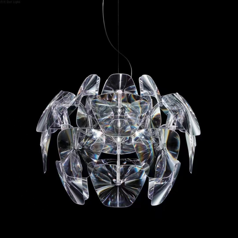
Pendant-style thin translucent programmes make gate cosmetics non-negotiable because the lit pieces are the product. Keep gate type, knit visibility and insert strategy on this page; return to the hub for the integrated thin-versus-transparent conflict, cooling overview and order-document checklist in the thin-wall moulded lighting case.
When multiple clear pieces share a fixture, demand consistent gate philosophy across the family so one part does not show a centre vestige while its neighbour hides a tunnel scar. Mixed strategies are allowed only when the appearance map explains why.
Upload the CAD with lit-face masks and gate preferences, then request a quote for translucent moulding. Contact projects@6cproto.com or WhatsApp +86 180 2219 4001 for DFM before gate steel is committed.
FAQ
Can polishing remove a gate blush on clear PC?
Light haze from handling sometimes improves with careful polish, but shear blush and residual-stress marks at the gate usually remain visible under backlight. Relocating or resizing the gate, or changing process window, is more reliable than chasing the witness with abrasives that also distort optics.
Are pin-point gates safe on thin diffuser domes?
They can fill efficiently but often leave a centred witness and high local shear on stiff optical melts. Many lighting tools move to edge or tunnel gates on a rim instead. Prove the vestige under the production LED before freezing a pin gate on the optic.
Does a hot tip eliminate knit lines on multi-window clear parts?
No. Hot tips change thermal history and vestige style, but multiple flow fronts still meet. Knit placement is a filling-pattern problem. Use simulation and lit-face masks to steer welds regardless of runner type.
Should gate inserts be specified on a bridge tool?
Not always. Short bridge volumes may not wear a gate enough to justify inserts. Specify them when resin shear is high, cosmetic land is critical, or the bridge tool may transfer into longer production. Ask for a wear note in the tool design review either way.