

Explore Injection Molding Design & Tooling
A gate mark can be acceptable and still be unacceptable in the wrong place. Hiding it inside an enclosure may solve an appearance problem while putting a raised remnant against a mating component. Specify injection molding gate vestige by location and consequence before asking a supplier to make it less visible.
Gate vestige vs witness line
Specify injection molding gate vestige as a controlled local feature with an approved location, allowable profile, and finishing condition. Distinguish it from parting-line witness, flash, and flow-related appearance. Agree cosmetic inspection conditions separately from dimensional clearance, then approve representative samples before treating a gate mark as acceptable for the batch.
The distinction is practical: a gate remnant belongs to the material-entry location, while a witness line may describe evidence of a tooling boundary. Supplier terminology can overlap, so annotate the actual feature rather than relying on its name. A flat-looking mark can still differ in gloss or color from the surrounding surface.
Protolabs’ gating guidance explains how gate style, material, and geometry affect the remaining mark. Use that relationship to discuss options, not to demand a universal invisible gate. The delivered part must satisfy the location-specific acceptance requirement.
Where cosmetics matter on the part
Divide the part into surfaces according to visibility, touch, and function. A broad front panel may need a cosmetic limit, a grip edge may need a tactile limit, and a hidden rib may need only a clearance check. Do not assign every surface the same rule merely because it shares one part number.
Mark prohibited gate regions and explain the reason. A sealing land, sliding surface, optical feature, label area, or assembly contact can need protection even when it is rarely seen. Identify the viewing direction for exposed faces and the assembled condition in which the evaluation occurs.
BYK’s appearance guidance for consumer electronics treats color and gloss as contributors to the overall result and notes measurement placement issues on small parts. A tiny gate area may require a different inspection approach from the adjacent flat panel. Agree the method rather than applying an instrument number where the geometry cannot support it.
How to write acceptance criteria
Write acceptance criteria that a second inspector can apply. Identify the allowed region, local dimensional envelope, permitted finishing, and cosmetic comparison method. Keep raised material, depressions, discoloration, and exposed substrate damage as distinct conditions so that one general statement does not conceal several different defects.
For clearance-critical areas, use the controlled drawing to define the allowable surface relative to the relevant datum or mating geometry. ASME Y14.5 provides a language for geometric requirements; it does not supply a ready-made vestige limit for every molded component.
For appearance, state the approved reference, lighting, distance, orientation, and whether magnification is part of acceptance. Decide whether a close-up is diagnostic evidence or the inspection condition itself. A mark visible only in a highly enlarged photograph should not automatically fail a part intended for unaided evaluation, unless that is the agreed requirement.
Table: gate types and typical marks
Gate choice changes the likely mark and the tooling work, but does not alone determine acceptance. Compare the proposed location and finishing method with the actual part. Ask the supplier to show the gate detail on the DFM view before committing to a cosmetic promise.
Mold-Masters’ drawing portal includes system gate details, illustrating that the interface is an engineered tooling feature. Review the selected detail rather than assuming every valve or thermal gate leaves the same surface.
| Gate concept | Potential evidence on the part | Location question | Approval check |
|---|---|---|---|
| Edge or tab gate | Trimmed region at a boundary | Does trimming affect an edge or mating surface? | Profile and permitted finishing |
| Tunnel-style gate | Localized separation mark | Can the gate reach a permissible region? | Remnant, tearing, and repeatability |
| Thermal hot-tip gate | Localized gate appearance and possible surrounding variation | Is the face visible or functionally sensitive? | Local profile and appearance sample |
| Valve gate | Pin-related local witness | Is the selected detail appropriate for the finish? | Representative molded surface |
These are possible mark categories, not promised defect levels. Material, tooling condition, and processing still need review.
Sample approval photos
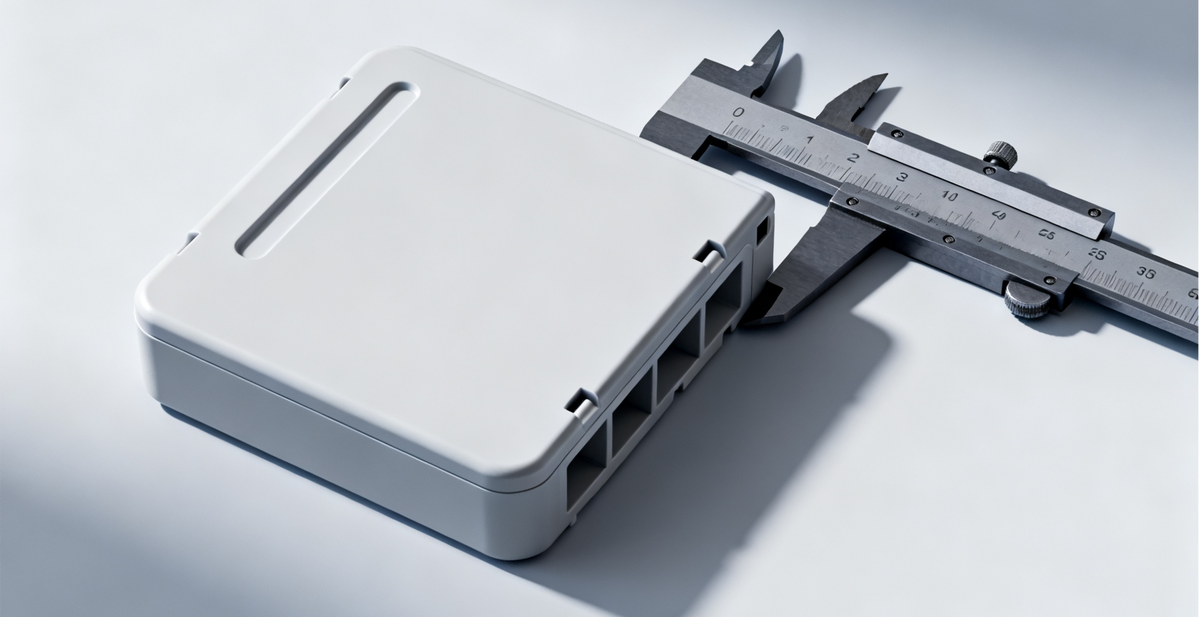
Capture a general view and a controlled close-up of the same identified sample. The general view establishes where the mark sits on the component; the close-up helps document its type and boundary. Include a scale reference where a dimension matters and avoid reflections that conceal the feature.
Record the part revision, cavity, material, finish, sample identity, and inspection condition with the photographs. If a boundary sample defines the acceptable appearance, retain the physical sample and clarify whether the photograph is merely a reference. Camera settings and screens can change the apparent contrast.
BASF’s injection molding troubleshooter separates multiple appearance defects, including weld lines and sink marks. Label the observed condition accurately when requesting a correction. A photograph of an unexplained line should not become a gate correction request until the tool location and defect mechanism have been checked.
FAQ
These questions address specification details that should be settled before sample approval.
Can the inspection team reject every visible witness line?
Only if that is the agreed acceptance requirement and the selected manufacturing route can meet it. Otherwise, identify the permitted locations and comparison conditions before production. A visible tooling witness is not automatically equivalent to raised flash, damage, or functional interference. The inspection decision should follow the controlled criterion for the specific surface.
Does a valve gate guarantee that no finishing will be needed?
No. The selected gate detail, resin, process, and surface requirement determine whether the result is acceptable as molded. Review representative samples and identify any authorized secondary work in the quotation. A process name should not replace a local dimensional or cosmetic limit, especially where the gate lies near a contact or sealing feature.
Can a photograph replace the retained boundary sample?
It can support communication, but it may not reproduce the surface contrast, gloss, or tactile condition reliably. If appearance is defined by a physical boundary sample, retain and identify that sample and its viewing conditions. State which evidence governs acceptance. Where a dimensional envelope controls the feature, use the agreed measurement rather than estimating size from an image.
Related process selection notes
Choose the process change that addresses the actual acceptance failure. Relocating a gate, changing its detail, adding trimming, or adjusting the cosmetic requirement are different decisions with different consequences. A relocated gate may change filling and the location of other visible or structurally relevant features.
Use prototype injection molding to evaluate uncertain appearance or clearance requirements when representative tooling and material are available. State which gate details will carry over to the intended production tool. A sample made with another gate arrangement cannot validate the final witness location.
If painting or local finishing is proposed, check whether it changes fit, texture, or the required contact surface. Keep that operation in the approved process rather than allowing informal handwork to define the standard. The acceptance sample should represent the condition the supplier can repeat, including the authorized finishing sequence.
Internal links and next steps
Send the controlled CAD and drawing with a marked surface map, allowed gate regions, prohibited regions, and the reason for each restriction. Include the intended resin and finish, visible assembly views, and any mating geometry needed to assess clearance. Identify which decisions remain open for DFM.
For the plastic injection molding review, request a proposed gate location, relevant tooling detail, and sample acceptance plan. Use the standards and tolerances reference as background while retaining the project-specific limits on the drawing.
Ask 6CProto to review the cosmetic zones and gate acceptance criteria with your quote. Approve both the location and the finished sample condition so that purchasing and inspection apply the same requirement to later production.