

Laboratory instruments are precision machines with a tolerance story that is different from production hardware: they carry optics, sensors, and moving stages that must stay aligned through temperature changes and years of service, and they are often built in small quantities where every part is a first article. The machined components — benches, mounts, housings, and mechanism parts — set the instrument’s accuracy, and the machining decisions are really stability and alignment decisions. A lab instrument part that measures well on arrival but drifts with temperature or relaxes after machining is a part that fails the instrument even though it passed inspection.
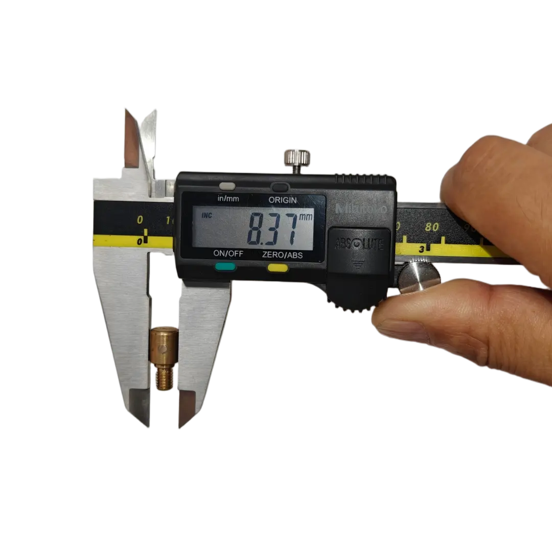
Instrument hardware: where precision actually matters
Not every dimension on an instrument part is precision-critical; the precision belongs on the features that carry the measurement. Optical mounts need their datum faces and bores; stages need their guide surfaces and drive features; sensor housings need their alignment seats; and frames need the mounting interfaces that hold the subsystems in relation. The drawing should mark the precision features and let the rest follow general tolerances, because an instrument part with every dimension tight is an instrument part that is expensive to make and no more accurate. The precision story is in the relationships — the parallelism of two faces, the position of a bore to a datum — not in the nominal sizes alone.
The measurement plan should verify those relationships with the same coordinate method the instrument relies on, and the inspection report should state the datum scheme it measured to. A report that measures individual dimensions without the datum relationships cannot prove the instrument’s alignment.
Material stability for optical and analytical benches
Instrument materials are chosen for stability as much as for strength. Aluminum with a controlled temper and stress relief is the common bench material because it is light and machines well, but its thermal expansion means the design must account for temperature; stainless and low-expansion alloys appear where the alignment budget demands more; and granite or ceramic appears in the highest-stability benches as a separate structure. The machined component’s stability depends on the material condition — a stress-relieved plate holds its machined geometry better than one with high residual stress — and on the machining sequence that removes material evenly. The drawing should state the material condition and the stability expectation, because the shop cannot choose a stable material that the drawing does not specify.
Thin, asymmetric machined features are the stability risk: removing a large share of the stock from one side can release stress and move the part. The design should balance the material removal and plan the machining sequence with the shop, and the first article should be measured, allowed to settle, and re-measured to confirm stability.
Contamination and cleaning constraints
Analytical instruments are sensitive to contamination — particles, residues, and outgassing can affect measurements — so the machined parts carry cleanliness requirements that the drawing must state. The cleaning method, the packaging, and the handling belong in the specification for the parts that enter the measurement path, and the machining process should avoid embedding contaminants in the surface. Materials that outgas are excluded where the instrument is sensitive, and the surface finish is specified where particles could shed. A lab instrument part that is machined perfectly and shipped with chips in a thread has failed its real requirement, so the cleanliness and packaging notes are functional, not cosmetic.
The cleaning and packaging requirements should be confirmed with the shop before quoting, because they add process steps that belong in the price and the schedule.
Designing for serviceability and adjustment
Laboratory instruments are serviced over long lives, and the machined parts should support adjustment and maintenance. Adjustment features — slots, oversized holes, shim points, and threaded adjusters — let the instrument be aligned in the field without machining new parts, and the design should place them where the instrument will need them. Serviceable joints should use fasteners that can be removed and reinstalled without losing position, and the parts that wear should be replaceable rather than integral. The serviceability design is part of the instrument’s total cost: a part that is cheap to make but expensive to service is not the economical choice for an instrument that will be maintained for a decade.
The drawing should mark the adjustment ranges and the reference features, so the field service can align the instrument to the intended datum scheme rather than improvising.
Working with a supplier on R&D instrument parts
R&D instrument parts are often low-volume, iterative, and precision-critical, and the supplier relationship should match that profile. The supplier should review the drawing for the datum and stability story, machine the precision features in controlled setups, and provide the inspection report tied to the datum scheme. The revision control matters more than volume: a one-off part that is revised and re-machined should carry the same documentation discipline as a production part, because the instrument’s validation depends on knowing what was built. The supplier that asks about the instrument’s function and the stability requirement is the supplier that can machine the part to support it.
The CNC machining service and the precision guides on this site cover the manufacturing; the instrument requirements above are what turn a machined bracket into a metrology-grade component. When the precision features, the material stability, and the cleanliness notes are on the drawing, the part is specified for the instrument’s real demands.
Verifying instrument parts and working through iterations
The verification of an instrument part starts with the functional features: the datum relationships that carry the measurement, measured with the coordinate method the instrument relies on. The part should be measured, allowed to settle, and re-measured, because the stability that the instrument needs is confirmed by the second measurement matching the first. The cleanliness and the finish are verified on the surfaces that enter the measurement path, and the packaging is confirmed to protect the part to the instrument bench. The verification record should state the datum scheme, the measurement method, and the stability result, so the instrument team can trust the part without re-qualifying it. A part that is verified once on the bench and again after shipping is a part whose stability claim is evidence rather than hope.
R&D instrument parts iterate, and the iteration should carry the documentation. Each revision should be verified against the same functional features, with the change and its effect recorded: a material change is verified for stability, a datum change is verified for the measurement, and a finish change is verified for the cleanliness. The revision record becomes the instrument’s quality history, and it is what the final validation and the service manual reference. The supplier relationship for instrument parts works best when the shop understands the function: a shop that knows the part carries an optical bench will machine the datum features in the same setup, ask about the stability, and flag the features that the drawing does not control. That collaboration is what turns a machined part into a component the instrument can trust for years.
The drawing that communicates the instrument requirements includes the functional features with their relationships, the material and its condition, the cleanliness and packaging notes, and the inspection method. It marks the datum features the measurement relies on, the stability expectation, and the surfaces that must stay clean. The shop that machines from that drawing can hold the relationships, choose the stable material, and plan the cleanliness; the shop that receives only a geometry file cannot. The instrument part specification is a collaboration between the design team and the machinist, and the drawing is the record of that collaboration. When the requirement is on the drawing, the machined part supports the instrument’s accuracy instead of limiting it — and the instrument measures what it was designed to measure, because the hardware that carries the measurement was machined for the job.
One more instrument detail: the thermal environment of the lab and the instrument’s warm-up. Many analytical instruments are calibrated at a defined temperature after a warm-up, and the machined parts should be stable across that condition. The drawing should state the operating temperature range and the stability expectation, and the first article should be measured at the operating condition. The instrument part that is specified for its real thermal life is the part that holds the calibration; the one specified for the bench temperature can drift when the instrument runs warm.
Finally, keep the measurement and stability data with the part. The first-article report, the re-measurement after settling, and the cleanliness record form the instrument part’s quality file, and the file is what the instrument team and the future revisions reference. When the part is revised, the file shows what changed and what was re-verified; when the instrument is serviced, the file explains the part’s design intent. The documentation is the last feature of an instrument-grade machined part, and it is the feature that makes the part trustworthy over the instrument’s long life.
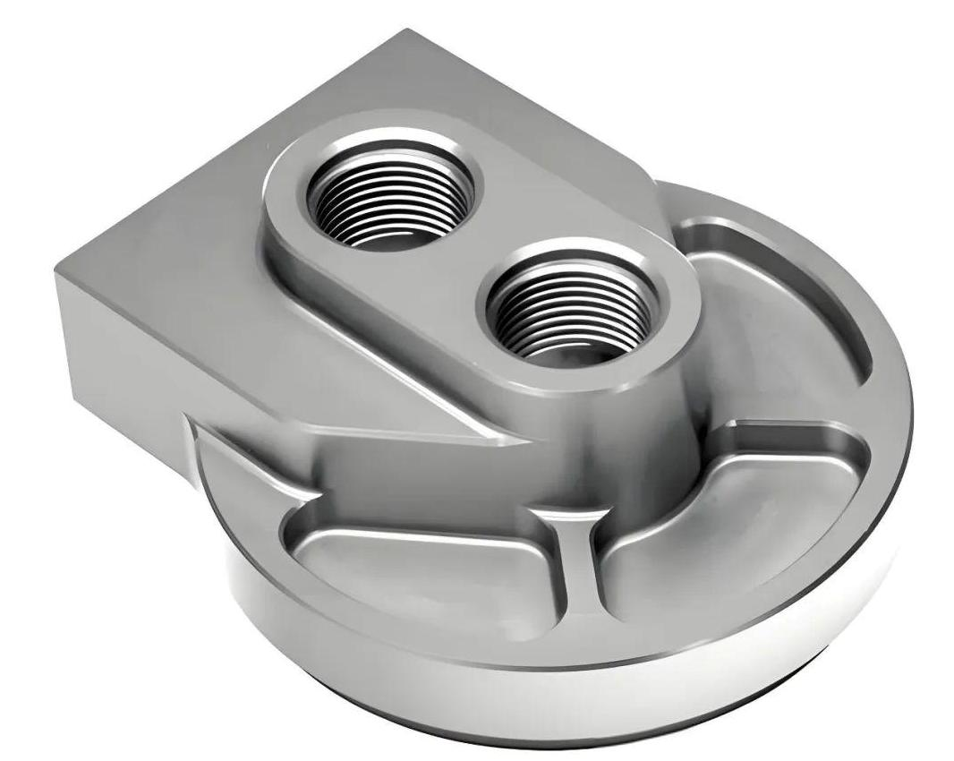
If you are sourcing machined parts for a laboratory instrument and want the precision, stability, and cleanliness plan reviewed before machining, the 6CProto CNC team can work from your measurement requirement to the drawing and the inspection plan.