

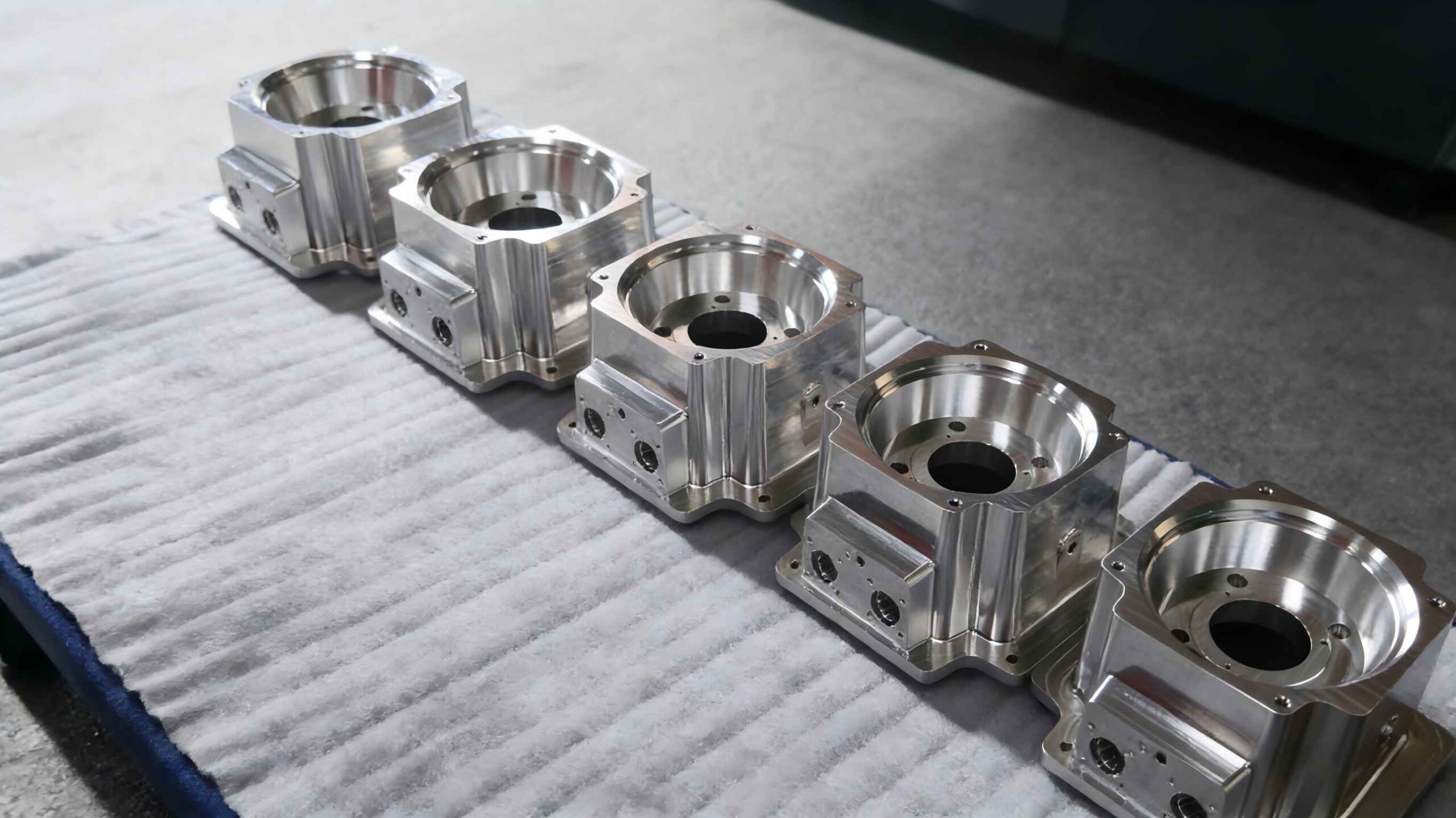
A machined enclosure is usually chosen for one of three reasons: the quantity is too low for a casting or a molding tool, the wall sections and interfaces are too demanding for sheet metal, or the product needs a sealed, machined face that only a cutting tool can produce. The consequences of the design decisions made on that part extend further than on most components, because the enclosure carries every other part in the assembly. This guide covers what makes a machined case expensive, how sealing surfaces and bosses should be designed, and how to prepare a request that avoids a round of re-quoting.
What makes a machined enclosure expensive?
Depth, thin walls, and the number of setups.
Cost follows the volume of material removed and the number of times the part has to be repositioned, so a deep pocket with thin walls is the most expensive shape a housing can take.
Material removal is the first driver. An enclosure is mostly a cavity, so machining it means removing a large volume of stock as chips, which consumes machine time in proportion to the volume removed rather than to the finished part. A deep pocket with a small opening is the worst case, because the tool has to reach into it with limited rigidity and at reduced feed rates.
Setups are the second driver. Every feature on a different face requires the part to be repositioned, and each setup costs fixturing time and introduces a small positional error. An enclosure with features on five faces is considerably more expensive than one that can be completed from two directions, even when the material volume is identical.
Wall thickness is the third. A thin wall is weaker, so the part deflects under clamping and cutting forces, which forces lighter passes and slower speeds. Where an enclosure needs a thin wall for weight or for internal clearance, the design is achievable but the cost reflects the difficulty. Keeping sections as uniform as the function allows, and avoiding unnecessarily deep pockets, are the two changes with the largest effect on price.
How do wall thickness and depth interact with tool access?
Depth limits the tool, and the tool limits the geometry.
A pocket that is deep relative to its width requires a long, slender cutter that deflects, so achievable accuracy and surface finish both fall as the depth-to-width ratio rises.
The practical constraint is tool rigidity. A cutter that reaches deep into a pocket is supported only at its shank, so it bends under cutting load, which produces chatter, poor finish and dimensional error. The response is to reduce the depth of cut and the feed rate, which extends the machining time, or to use a larger cutter, which requires the pocket to be wider.
Corner radii follow from the same logic. Every internal corner carries the radius of the cutter that produced it, and a deep pocket requires a larger cutter to reach the bottom without deflecting, so its corners are larger. A design that calls for a sharp internal corner at the bottom of a deep pocket cannot be produced as drawn; either the radius is accepted or the feature is produced by another process such as EDM.
Where a design is close to those limits, two adjustments help. Reducing the depth of a pocket by raising the floor, or by making the enclosure from two pieces that assemble, changes the geometry into something a standard cutter can handle. The CNC machining service covers the process side of those decisions.
How should sealing surfaces and gasket geometry be designed?
As a controlled compression system.
A sealed enclosure works when the gasket is compressed by a known amount across a continuous, flat, adequately finished sealing face.
Three elements have to work together. The sealing face must be flat and smooth enough that the gasket can conform to it, which usually means a machined surface rather than an as-cast or coated one. The gasket must be compressed within the range it was designed for, neither so little that it does not seal nor so much that it takes a permanent set. And the fasteners must distribute that compression evenly around the perimeter.
A gasket groove is one way to control compression. The groove holds the gasket in position during assembly and limits how far it can be compressed, which makes the seal more repeatable than relying on the fastener torque alone. The groove’s width and depth have to match the gasket’s cross-section, and its corners need a radius the cutter can produce. Where the gasket sits in a groove, the sealing surface opposite it must still be flat enough for the gasket to seal against.
Surface finish matters more than it appears. A sealing face with visible tool marks provides a path for leakage along the grooves, which is why sealing surfaces are usually specified with a finer finish than the rest of the part and machined in a single continuous operation where possible. Masking protects them from any subsequent coating, because a coated sealing face changes the compression and may not bond the way the base metal does.
| Factor | Effect on cost | Design response |
|---|---|---|
| Pocket depth | Long slender tools; slower cutting | Reduce depth or split the part |
| Wall thickness | Deflection forces lighter passes | Keep sections uniform |
| Number of setups | Fixturing time and positional error | Consolidate features onto accessible faces |
| Internal corner radii | Small radii need small, slow tools | Accept the largest radius the function allows |
| Sealing face finish | Additional finishing operation | Specify only where the seal requires it |
| Coating | Masking labour and dimensional change | Mask sealing, mating and threaded features |
How should screw bosses and threads be designed?
As load paths, not as holes.
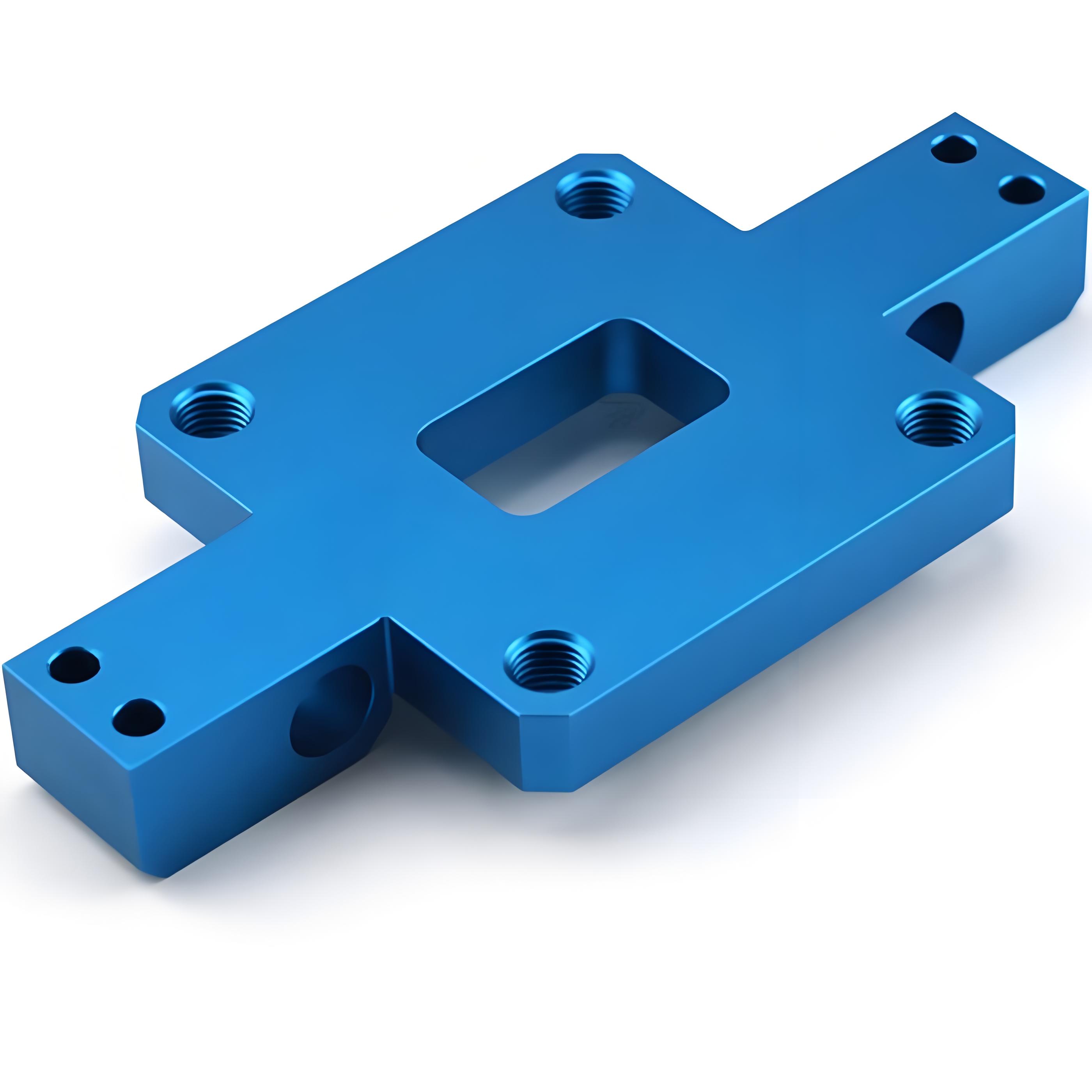
A boss that takes a screw carries the assembly load, so its wall thickness, its junction with the parent wall and the thread strategy all matter.
The thread is usually the first decision. A tapped hole in aluminium is adequate for a joint assembled once or twice, but the thread wears with repeated assembly and the load is carried by relatively few engaged threads. A metal insert pressed or bonded into the boss distributes the load and survives repeated assembly, and it requires a larger boss diameter and a precise hole, both of which are machining operations rather than design afterthoughts.
Boss wall thickness follows from the thread and the material. The boss must have enough wall to resist the hoop stress from the fastener without cracking, and enough material around it at the base to transfer the load into the enclosure wall. A boss standing at the corner of a thin wall is the weakest arrangement; a boss blended into the wall with a fillet and supported by a rib is much stronger.
Fastener spacing then determines how evenly the joint closes, which matters most where the enclosure is sealed. Wide spacing allows the cover to bow between fasteners, reducing the compression on the gasket in the middle of each span. Where a seal has to be continuous, the spacing is set by the stiffness of the cover rather than by convenience, and adding fasteners is often cheaper than thickening the cover.
How should material and finish be chosen?
By weight, corrosion and conductivity requirements.
Aluminium is the default for machined housings, steel is chosen for strength or magnetic properties, and the finish follows the environment and the appearance requirement.
Aluminium machines quickly, is light, and conducts heat well, which makes it the natural choice for electronics housings where the case also acts as a heat path. Its corrosion resistance depends on the alloy and on the environment, so a coating or anodized finish is often specified. The grades available for machined parts are listed on the aluminium material page.
Steel is chosen where strength, stiffness or magnetic shielding is required, at the cost of weight and of the need for a protective finish. Stainless is used where corrosion resistance matters without a coating, though it machines more slowly and costs more. Where electromagnetic shielding is a requirement, the conductivity of the enclosure material and the continuity of the seams matter more than the finish, since a coated joint can interrupt the shielding path.
Finish selection then follows the environment. Anodizing is common on aluminium for appearance and corrosion resistance; powder coating provides a thicker, more durable film where the dimensional consequences can be managed; and plating is used where conductivity or a specific appearance is required. Each has its own masking requirements, which is why the finish decision belongs with the design rather than after it.
What should be inspected, and what should be in the RFQ?
Inspect the interfaces; specify the interfaces.
Inspection focuses on the features that decide assembly and sealing, and the request should describe those same features rather than the part as a whole.
The inspection scope on an enclosure usually covers the sealing face flatness, the locations of the mounting features, the depths of pockets that accommodate components, and the fit of the cover or lid. Those are the features where a small deviation prevents assembly, and they are the ones worth measuring rather than the entire part. Where the enclosure is sealed, a leak test may also be specified, and its method belongs in the request.
The request should then describe what matters. The quantity, the material, the tolerances on the interfaces, the finish per surface, the features that must be masked and the date the parts are needed. Adding the function of the enclosure, whether it houses electronics, carries a load or has to seal, allows the design review to raise the right questions. 6CProto reviews enclosure designs for manufacturability before production and returns a DFM report with the quote, which is where pocket depth, corner radii and gasket geometry can be resolved before material is cut.
Designing a machined enclosure that quotes well
A machined enclosure is economical when the design respects what a cutting tool can do. Reducing pocket depth, keeping walls uniform, accepting the corner radii the tool produces and consolidating features onto accessible faces all lower the price without changing the function. Sealing adds a second set of requirements, all of which depend on the flatness of the sealing face and the even distribution of fastener load.
The practical sequence is to design the enclosure around its interfaces, then confirm with a manufacturability review before the drawing is released. That review is where pocket depth, boss geometry, corner radii and the sealing strategy are tested against the process, and it costs far less than discovering the same issues at first article. The routes available alongside machining, and when each is appropriate, are described on the CNC machining page and in the comparison of enclosure processes covered elsewhere on the site. The tolerance framework for those interfaces is set out on 6CProto’s standards and tolerances page, with the quality practices behind inspection published by NIST MEP.
FAQ
Why are machined enclosures more expensive than sheet metal ones?
Because they remove a large volume of material and require multiple setups, while a sheet metal enclosure is formed from thin stock with little waste. A machined case is chosen when the design needs wall sections, sealing faces, or interfaces that sheet metal cannot provide at the required accuracy, or when the quantity is too low to justify tooling. The cost is the price of those capabilities rather than of the process being inefficient.
How deep can a pocket be machined?
Depth is limited by tool rigidity rather than by a fixed figure. A pocket that is deep relative to its width needs a slender cutter that deflects, which forces lighter passes, reduces accuracy and leaves a poorer finish. The practical response is to reduce the depth, widen the pocket, or split the enclosure into two parts that assemble. A manufacturability review will identify which pockets are near the limit.
Should enclosure threads be tapped or use inserts?
For a joint assembled once or twice, a tapped hole in aluminium is usually adequate. For a cover that will be removed repeatedly, a metal insert carries the load more reliably and survives more assembly cycles, because the load is distributed over more material than a tapped thread in aluminium provides. Inserts require a larger boss and a precise hole, so the decision belongs early in the design.
What surface finish does a sealing face need?
It needs to be flat and smooth enough that the gasket can conform and seal, which usually means a machined finish from a single continuous operation rather than an as-machined surface from several setups. Visible tool marks provide paths for leakage along the surface. Where the part will be coated, the sealing face is normally masked so the gasket seats against metal rather than against a coating. The standards, materials data and regulatory framework referenced in this article are published by ASTM committee B08, ASTM D3359, ASTM committee D20, ASTM committee E28.
If an enclosure has to seal, hold a load or house electronics, send the model with the interfaces that must be exact and the finish for each surface. 6CProto reviews enclosure designs for manufacturability and returns a DFM report with the quote, so pocket depth, boss geometry and the sealing strategy are settled before machining. Upload the file at the 6CProto quote page or send it to projects@6cproto.com.