

Three interfaces can decide whether a machined enclosure works: the electrical seam, the environmental seal, and the fastened joint. They share the lid but do not have identical acceptance requirements. CNC machined enclosures need a coordinated drawing that preserves all three functions after machining, finishing, and assembly.
Seam and gasket groove design
Design CNC machined enclosures by defining the seam’s electrical function, the gasket’s required compression and environment, and the joint’s fastener loading. Specify the finished contact surfaces, groove geometry, datum relationships, and assembly state together. Validate the actual assembled system rather than inferring shielding or sealing performance from the metal material or enclosure appearance.
Parker Chomerics’ shielding and gasketing guidance describes the role of an EMI gasket in maintaining current continuity across a shield. That is a different requirement from excluding water or dust, even when one gasket is proposed to provide both functions.
Use the selected gasket supplier’s geometry and material guidance. Parker’s O-Ring Handbook addresses gland design and squeeze for its sealing context. Do not copy an O-ring groove into a conductive gasket design without confirming the actual gasket. The machined-enclosure review should identify the exact component and its intended functions.
Fastener strategy and thread inserts
Choose fasteners and thread engagement as part of the complete joint. The lid must distribute compression without excessive bending or local damage, and service requirements may demand repeated opening. A screw count chosen only from available space can leave a different compression condition between fasteners than near them.
NASA’s Fastener Design Manual is a reference for threaded-joint design considerations. Its existence does not prescribe one torque or spacing for this enclosure. Specify the actual screw, thread material, engagement, assembly method, and required service behavior.
If thread inserts are proposed, identify the insert type, installation method, and any effect on wall thickness, sealing, or electrical contact. Review repeated assembly with the selected joint rather than assuming an insert guarantees unlimited reuse. Keep tightening requirements on the controlled assembly specification and avoid substituting a generic torque table for a validated joint condition.
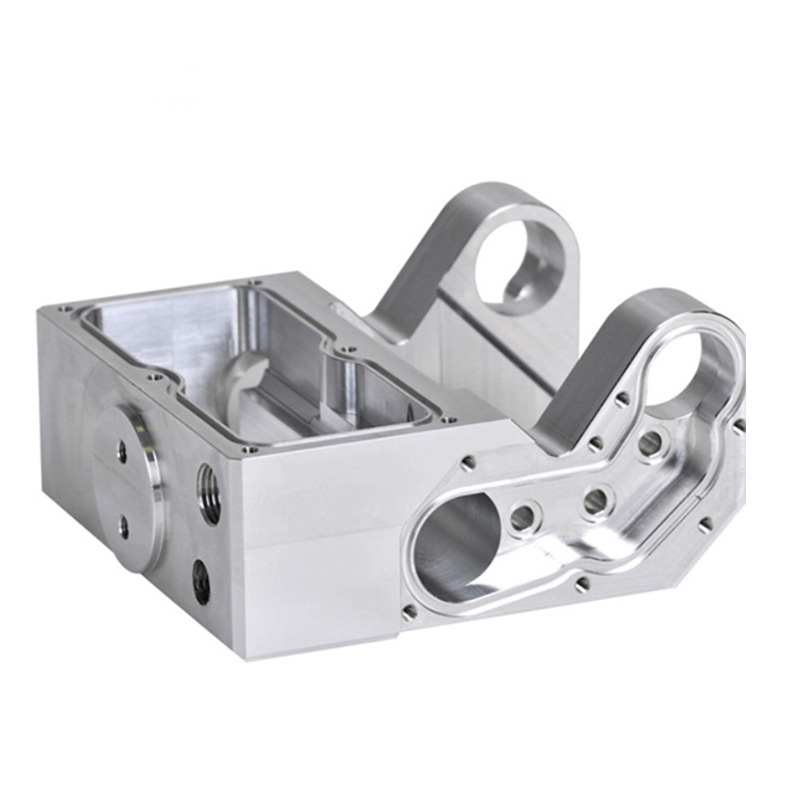
Cosmetic faces vs functional seals
Separate cosmetic finish from functional contact. A coating can create the desired appearance while changing an electrical contact region or the final groove dimensions. Mark the surfaces that must remain conductive, the surfaces requiring protection, and any masked region whose boundary matters to the seal.
State the finished texture requirement where the gasket or mating function needs it. Mitutoyo’s roughness resource addresses the measurement topic, but a general smooth finish note does not identify the required parameter, direction, or evaluation condition.
Check the tolerance stack before approving the groove. In a hypothetical example, free gasket height is 2.0 ± 0.1 mm and assembled gap is 1.6 ± 0.1 mm. Using squeeze = (free height − gap) / free height, the extreme combinations give approximately 10.5% and 28.6%. These are illustrative geometric results, not recommended squeeze limits or a validated gasket design. Actual supplier limits and lid behavior still govern.
Table: aluminum vs stainless enclosure notes
Compare aluminum and stainless steel against the enclosure’s actual environment, structural needs, finish, and contact system. Neither material name establishes shielding, corrosion compatibility, or sealing performance for the assembled product. Exact grade and surface condition belong in the specification.
For an aluminum enclosure, identify which finishing steps affect mating dimensions or electrical contact. For stainless construction, define the required grade and surface treatment rather than assuming every stainless alloy behaves alike.
| Decision | Aluminum route | Stainless route | Evidence to retain |
|---|---|---|---|
| Material identity | Specified alloy and condition | Specified grade and condition | Controlled material designation |
| Seam contact | Review coating and gasket interface | Review finish and gasket interface | Finished contact requirements |
| Fastened joint | Review thread and local wall design | Review thread and assembly conditions | Joint specification and service trial |
| Environment | Assess the full metal/gasket/fastener combination | Assess the full metal/gasket/fastener combination | Application-relevant exposure and function tests |
Let the assembly requirement determine the comparison rather than ranking materials by an isolated conductivity or corrosion label.
RFQ details
Supply both lid and base geometry with a common revision. Include the selected gasket, assembled gap, contact regions, groove dimensions, fastener pattern, thread requirements, material and finish, and the relevant functional tests. A base-only model may hide the tolerance stack that controls compression.
ASME Y14.5 provides a language for geometric requirements. Use the applicable convention to state the relationships between the groove, lid, mounting interfaces, and contact surfaces. Keep assembly-state dimensions distinguishable from isolated component measurements.
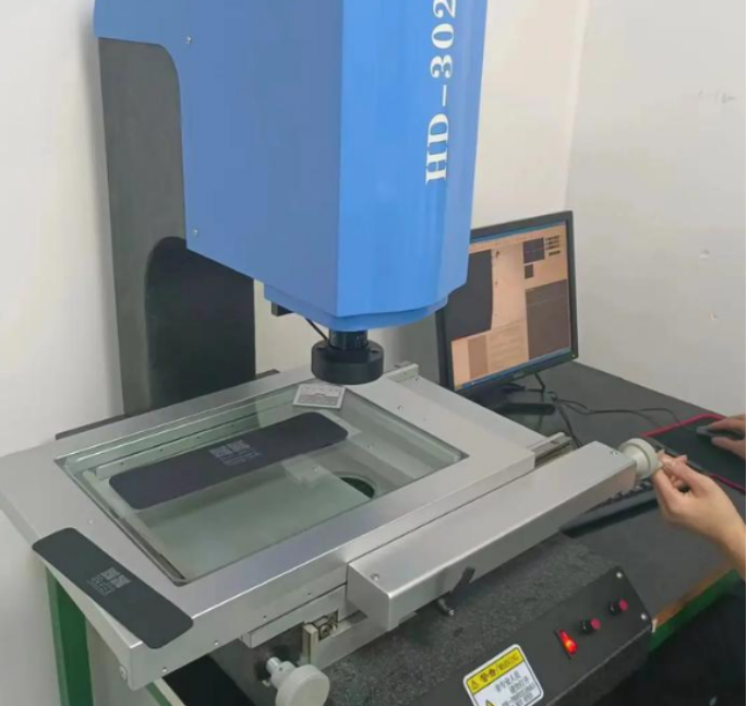
For the CNC machining RFQ, identify which regions are critical to function and what must be inspected after finishing. Ask the supplier to return the proposed process sequence and any access or masking concerns. Include the required quantity and service expectations without assuming that a generic enclosure description defines the inspection or test scope.
FAQ
These questions address specification details that should be settled before sample approval.
Does a conductive metal box automatically provide the required EMI shielding?
No. Seams, openings, contact surfaces, connectors, and the assembled configuration affect the result. Specify the electrical contact requirements and evaluate the relevant system performance. A material conductivity value or a machined-box photograph cannot substitute for the application test. Keep the gasket and finish conditions traceable to the tested assembly.
Can one gasket provide both environmental sealing and EMI contact?
It may be designed for both functions, but each requirement still needs evaluation with the actual gasket, groove, finish, and compression. Do not assume that an environmental seal is electrically suitable or that an EMI gasket meets the required exposure condition. Obtain the supplier’s guidance and verify the complete assembly against both functions.
Will adding screws always improve sealing?
Not necessarily. The result depends on lid stiffness, support, groove geometry, assembly loading, and the gasket. More fasteners can change the load distribution without resolving an incorrect compression stack or local distortion. Review the joint and test the representative assembly. A fastener pattern should follow the required interface behavior rather than an arbitrary spacing rule.
Related process selection notes
Choose the manufacturing route around the interfaces that require control. Machining can create pockets, mounting features, and grooves in one component, but the assembly still depends on the lid, gasket, fasteners, and finish. A process proposal should identify how those interfaces will be preserved through production.
For a consumer-electronics enclosure, decide whether the prototype evaluates fit, thermal layout, shielding, environmental protection, or user handling. These trials may require different levels of material and process representation. A visually convincing prototype does not prove every functional requirement.
Retain the gasket identity, assembly method, and test configuration with the approved sample. If a coating, lid thickness, screw, or gasket changes, assess the affected functions before accepting a reorder. The relevant evidence is the finished assembly under its required conditions, not simply the fact that its individual components meet nominal CAD dimensions.
Internal links and next steps
Close the drawing review with a clear division of acceptance evidence. Component inspection establishes the specified geometry and finish; assembly checks establish the required fit and compression behavior; appropriate system tests evaluate shielding or environmental performance. Avoid extending any one result beyond what was actually tested.
Ask the supplier to identify unresolved assumptions for groove access, masking, finished dimensions, and inspection. Keep any accepted design change controlled so that the next batch does not inherit an informal shop adjustment. The quotation should cover the work required to deliver the accepted component state.
Send 6CProto the lid, base, gasket, and contact-surface requirements for a quote and DFM review. Request review of the complete interface stack before releasing the enclosure for machining.