

A machined part fails its position callout at inspection, and the shop and the buyer disagree: the shop measured from the machined face it used as the setup, and the buyer measured from the datum the drawing named — a datum feature that the shop could not hold or measure in the same way. Datum selection is the part of GD&T that decides whether a tolerance is measurable and meaningful. The datum features are the reference points the part is made and measured from, and choosing them well — functional, stable, and accessible — is what turns a drawing into a part that passes inspection and assembles.
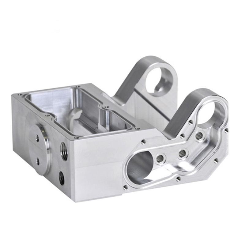
What a datum feature must do for the part and the CMM
A datum feature is the physical surface or feature that establishes a reference plane, axis, or point for the tolerances. It must do two jobs: it must represent the part’s function in the assembly, and it must be measurable — a feature the shop can hold and the CMM can probe repeatably. A datum that is functional but unmeasurable produces tolerances that cannot be verified; a datum that is measurable but not functional produces parts that pass inspection and fail in the assembly. The datum selection balances the two, and the drawing should name the features that carry that balance. The GD&T-basics guide covers the symbols; this page is the datum-selection decision that makes them work.
The datum features should also be large enough and stable enough to establish the reference: a small pad or a thin edge is a poor datum because the measurement repeats poorly.
Functional datums: mating surfaces, bores, and planes
The functional datums are the features that locate the part in its assembly: the face that bolts to the housing, the bore that locates the shaft, or the plane that the mechanism rides on. The primary datum should be the feature with the largest, most stable contact — usually a face — and the secondary and tertiary datums should follow the assembly’s constraint order. A part that is located by a face and two holes in the assembly should use those features as its datums, so the manufacturing and the inspection reproduce the assembly condition. The functional datum scheme is the one that makes the tolerances mean something in the product.
The datum order matters: the primary datum constrains the most degrees of freedom, and the measurement should follow the same order as the assembly.
The 3-2-1 scheme and how to apply it
The classic datum scheme for a prismatic part is 3-2-1: the primary datum face contacts three points and establishes the first plane, the secondary datum edge contacts two points and establishes the second plane, and the tertiary datum point establishes the third. The scheme constrains all six degrees of freedom and provides the reference for the position and orientation tolerances. The 3-2-1 scheme applies when the part is located by three mutually perpendicular features; cylindrical parts use a different scheme with an axis. The scheme should be chosen from the part’s geometry and its assembly constraint, and the drawing should mark the datum features with the datum symbols so the shop and the CMM use the same reference.
The 3-2-1 scheme is a starting framework, not a rule: a part located by a bore and a face needs a plane-and-axis scheme, and the analysis should follow the real constraint.
Common datum mistakes that make parts unmeasurable
The common datum mistakes are visible in the inspection disputes. Specifying a datum on a feature that is machined late in the process, so the earlier operations cannot reference it; choosing a datum that is too small or too flexible to measure repeatably; naming a datum that is not accessible to the CMM; and using different datums for different tolerances on the same part, so the features never align. Each mistake makes the tolerance unmeasurable or the measurement unrepeatable, and the drawing should be reviewed for the datum scheme before release. A datum review asks: can the shop hold this feature as the reference, can the CMM probe it repeatably, and does it represent the assembly?
The review should also check that the datum features are machined in the same setup or with the same reference, so the relationships the datums establish are actually controlled.
Communicating datum references to the shop
The datum scheme travels with the drawing, and the communication should be explicit: the datum symbols on the features, the tolerance callouts that reference them, and the note that states which features are the machining and inspection references. The shop should confirm that it can hold and measure the datum features as drawn, and the inspection report should state the datum scheme it measured to. A drawing that communicates the datum scheme produces a shop and a CMM that agree on the reference; one that leaves the datums implicit produces the measurement dispute that the tolerance was meant to prevent. The datum communication is the last step of the selection, and it is the step that makes the drawing executable.
The design-tips and standards guides on this site support the callouts; this page is the datum-selection decision. When the datum features are functional, measurable, and communicated, the part’s tolerances are verified against the same reference the assembly uses — and the part passes inspection because it was designed to.
Verifying the datum scheme on the first article
The datum scheme is verified on the first article, where the drawing’s assumptions meet the machined reality. The CMM measures the part with the drawing’s datum scheme and checks the repeatability of the datum features: a datum that probes inconsistently, a feature that is too small or too flexible, or a reference that the setup cannot hold shows up in the first-article measurement. The verification should also compare the measurement against the assembly condition — the part is checked the way it will be located in the product, and the tolerances are verified against that reference. If the first article fails or the measurement is unstable, the datum scheme is revised before production, not after a batch of disputed parts. A datum scheme that is verified on the first article is a scheme that the shop, the CMM, and the assembly all agree on.
The verification also sets the production inspection: the features that the datum scheme depends on are checked on a schedule, and the report states the datum scheme and the method every time. The measurement method is documented so a second inspector or a buyer’s CMM can reproduce the result. When the datum scheme is verified and the inspection is repeatable, the part’s tolerances are measured against the same reference the assembly uses — and the disputes that come from different references disappear. The datum choice is not a drawing convention; it is the agreement that makes the tolerance meaningful.
The datum review should also cover the machining sequence and the fixture. The datum features should be machined in the operations that establish the reference, and the fixture should locate the part on the same features the inspection uses, so the part is made and measured against the same scheme. A datum that is machined late in the process cannot be the reference for the earlier operations, and a fixture that locates on a different feature produces parts whose internal relationships drift. The review should trace the part through its operations and confirm that the datum scheme is consistent from the fixture to the CMM. When the machining, the fixture, and the inspection all use the same datum features, the part’s tolerances are controlled end to end, and the first article and the production parts agree.
Keep the datum plan with the drawing and the inspection report, so the reference scheme is consistent from design to measurement. The plan shows the datum features, the order, and the measurement method, and it prevents the drift that comes from reinterpreting the drawing part by part. The datum plan is also the training reference for the inspectors and the suppliers, because it explains why the references are chosen and how they are measured. The part that carries its datum plan is a part whose tolerances are measurable and meaningful — and the inspection that follows the plan is the inspection that both sides can trust.
Confirm the datum features with the shop before release, and keep the approved scheme with the drawing. The datum plan that both sides understand is the plan that produces parts that measure and assemble consistently.
Confirm the CMM program follows the drawing’s datum order, and verify the report states the datum scheme. The repeatable measurement is the proof that the scheme works.
The datum scheme is the agreement that makes a tolerance meaningful, and the review that confirms it with the shop and the CMM is the review that prevents the measurement dispute.
If you are choosing datum features for a machined part and want the scheme and the measurability reviewed, the 6CProto CNC and quality teams can work from your assembly to the datum plan and the inspection method.