

Micro manufacturing is not simply small-part machining. When feature sizes approach the scale of the tooling, the rules that make normal machining predictable stop applying, and the process has to be designed around stiffness, heat and measurement rather than around geometry alone.
What micro manufacturing covers
The term covers the production of components and features at a scale where conventional assumptions break down: small bores and slots, thin walls in hard materials, fine surface features, and parts whose overall size is modest while their internal detail is finer still. In aerospace work it appears in fuel and hydraulic components, sensor housings, instrument parts and any assembly where mass and envelope are tightly constrained.
| Scale challenge | What changes | Consequence |
|---|---|---|
| Very small cutting tools | Rapid wear, limited stiffness | Lower feeds, more tool changes, higher cost |
| Thin walls | Deflection and chatter | Support needed; light finishing passes |
| Fine features in hard alloys | Heat concentration | Coolant strategy becomes critical |
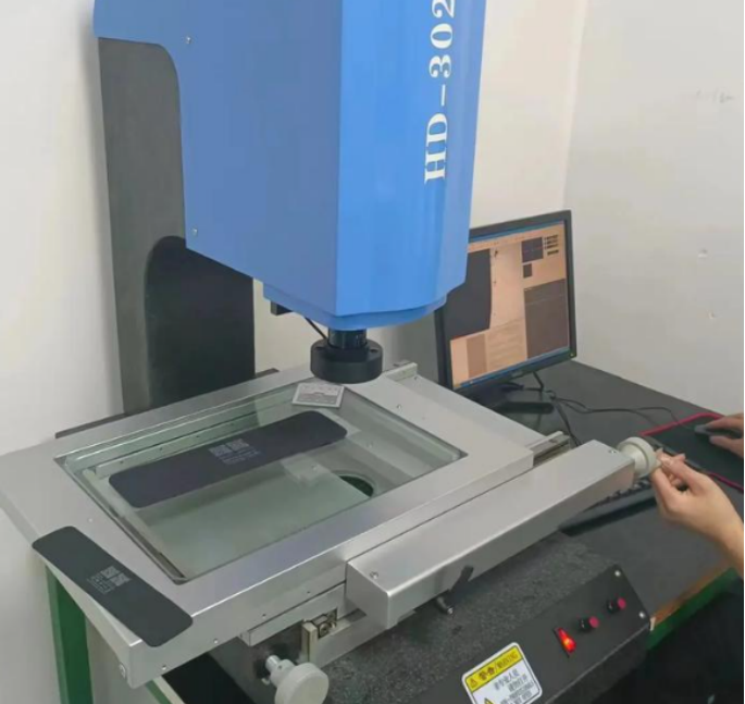
| Small tolerances | Measurement uncertainty is a larger share | Specialist inspection, controlled environment |
| Handling | Parts are fragile and easily lost | Containers, trays and process discipline |
Why micro machining is difficult
Three effects dominate. Tool stiffness falls with the cube of diameter, so a small cutter deflects far more under the same force, which limits how hard it can be pushed and therefore how quickly material can be removed. Heat concentration rises, because a small tool has little material to conduct heat away and the cutting edge is close to the shank. And chip evacuation becomes difficult, since a small flute has limited space, so chips are re-cut and the surface suffers.
The result is a process that is slow, tool-hungry and sensitive to setup. That is worth stating plainly, because micro manufacturing is often assumed to be a refinement of normal machining when it is closer to a different discipline, requiring smaller increments, more frequent tool changes and considerably more attention to the rigidity of every element in the system.
What micro features demand from tooling and clamping
Tooling has to be sharp, precisely balanced and changed frequently, because a worn edge on a small cutter produces a disproportionate effect on size and finish. Spindle speed must be high enough to keep the cutting edge working rather than rubbing, which in turn requires a spindle and holder capable of running accurately at that speed. And the coolant has to reach the cutting zone, which on micro features means high pressure or an air-oil mixture directed precisely rather than a general flood.
Clamping is the other half of the problem. Thin sections deflect under loads that would be negligible on a larger part, so soft jaws, custom fixtures and backing materials become standard practice rather than refinements. Where a feature is machined in a thin wall, the safest sequence often leaves supporting material in place until the last operation, then removes it in a way that does not distort what has already been produced.
Why tolerances behave differently at micro scale
A tolerance that seems reasonable on a large part can be unrealistic on a small one, because the measurement uncertainty becomes a significant fraction of it. If the inspection equipment’s uncertainty approaches the tolerance, the result is not evidence but an indication. That is why micro manufacturing programmes usually specify the measurement method alongside the dimension rather than only the limit.
Thermal effects also scale differently. A small part reaches the ambient temperature quickly, which helps, but the same small size means a modest temperature difference across the feature can consume a large share of the tolerance. In practice this pushes micro work towards controlled environments and towards parts being measured after they have stabilised rather than directly from the machine. Measurement practice is described by the NIST Manufacturing Extension Partnership.
Inspection methods that suit micro features
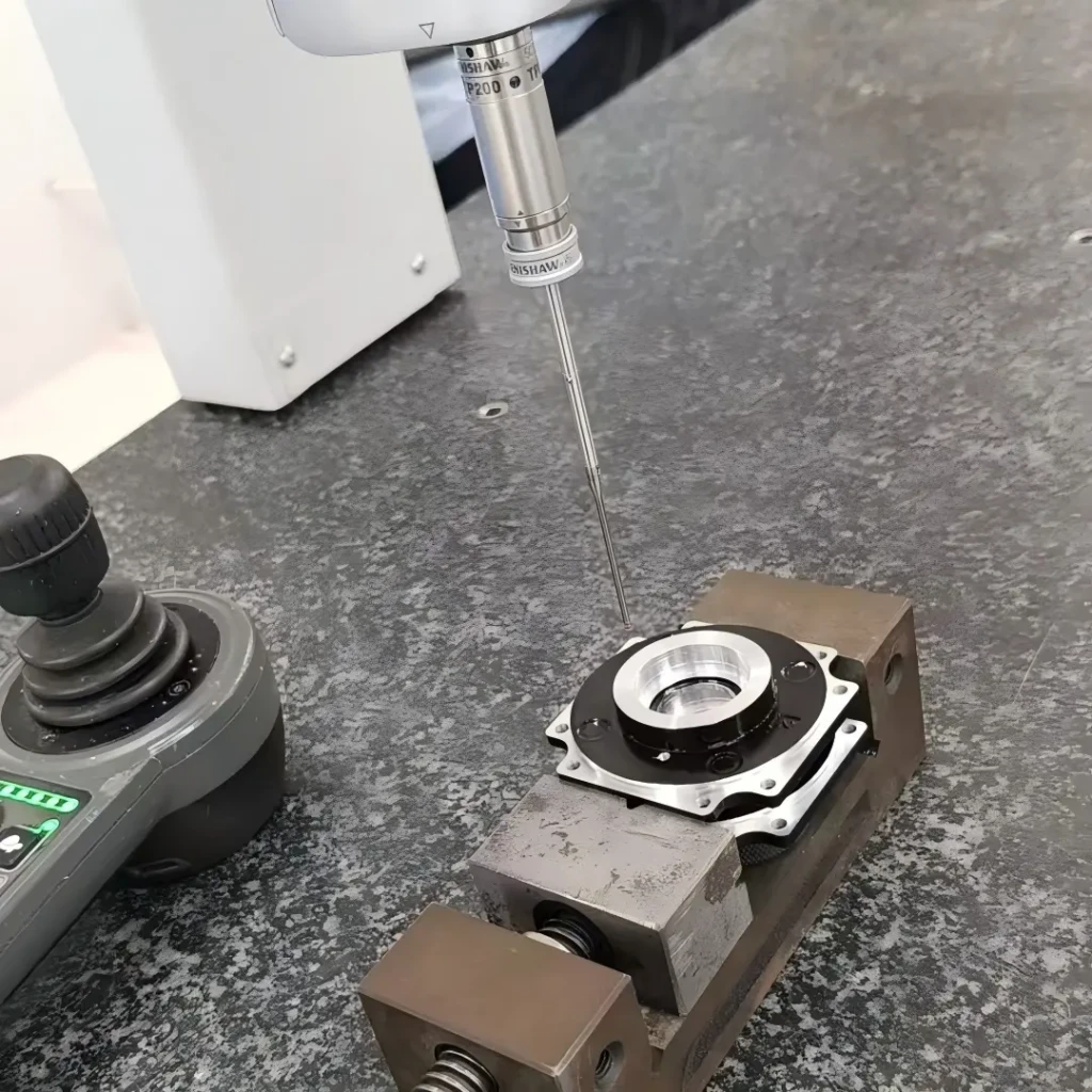
Three approaches cover most needs. Optical measurement and vision systems suit features that can be seen and are not hidden in a bore. Coordinate measurement with a small stylus works where contact is acceptable and the feature can be reached. And non-contact methods such as laser or structured-light scanning suit delicate surfaces, at the cost of requiring a reference for the data. For internal micro features, the choice is often between a small probe and a destructive check on a sample.
Two practical points matter. The measurement method should be agreed before production, because the design of the part sometimes has to accommodate the probe access rather than the other way round. And a first-article measurement should include the reference used and the conditions, since a micro dimension reported without those details cannot be compared later. Drawing conventions follow ASME standards, and surface terminology follows ASTM Committee B08.
How to brief a micro manufacturing project
State which features are genuinely micro-scale, because they drive the process choice and the cost more than the overall part size does. State the material, since a fine feature in titanium and the same feature in aluminium are different propositions. State the inspection requirement with the method, and say whether the part is a prototype or part of a production programme, because that changes how much process documentation is appropriate. And say what the part must do, so that where a tolerance is negotiable, it can be negotiated deliberately.
Two further points reduce risk. Mention any feature that must be reached by a measuring probe, so the geometry can be arranged accordingly. And expect the quotation to reflect tool consumption, because in micro work the tooling is a visible line item rather than an overhead. Material behaviour references are published by ASM International, the coolant and swarf obligations that apply to precision machining are set out by the US EPA, and process routes are described under precision machining and 3D printing.
Send the part with the micro-scale features and the inspection method you intend to use, and request a micro manufacturing quote with the tooling assumption stated.
FAQ
What is micro manufacturing?
Micro manufacturing covers components and features at a scale where normal machining assumptions break down, such as small bores and slots, thin walls in hard alloys and fine surface detail. In aerospace it appears in fuel, hydraulic, sensor and instrument components.
Why is micro machining difficult?
Tool stiffness falls sharply as diameter decreases, so small cutters deflect and cannot be pushed hard; heat concentrates at the edge because there is little material to conduct it away; and chip evacuation is poor, so chips are re-cut. The result is a slow, tool-hungry, setup-sensitive process.
What inspection methods suit micro features?
Optical and vision systems for visible features, coordinate measurement with a small stylus where contact is acceptable, and non-contact scanning for delicate surfaces. Internal features usually need a small probe or a destructive check on a sample, and the method should be agreed before production.