

Performance parts are usually defined by what they must survive rather than by how they look, and that changes the machining brief. The prototype has to carry the loads of the final part, in the final material, with the interfaces that will be used in testing, or the result proves very little.
What separates an accurate part from a stiff one
Accuracy and stiffness are different requirements, and a quote can satisfy one while failing the other. Accuracy means the dimensions land where the drawing says; stiffness means the part deflects as little as the design intends under load. A prototype can be dimensionally perfect and still perform differently from the production part if the material condition, the heat treatment or the surface condition on a stressed face was substituted for convenience.
| Requirement | What governs it | What to specify |
|---|---|---|
| Dimensional accuracy | Setup count, fixturing, tool condition | Datum scheme and the dimensions that carry the fit |
| Structural behaviour | Material grade, condition, fibre or grain direction | Exact grade and temper; anisotropy where it matters |
| Fatigue life | Surface condition on stressed faces, edge radii | Finish and radius callouts on those faces only |
| Repeatability | Process stability across the batch | Inspection record across the run, not one part |
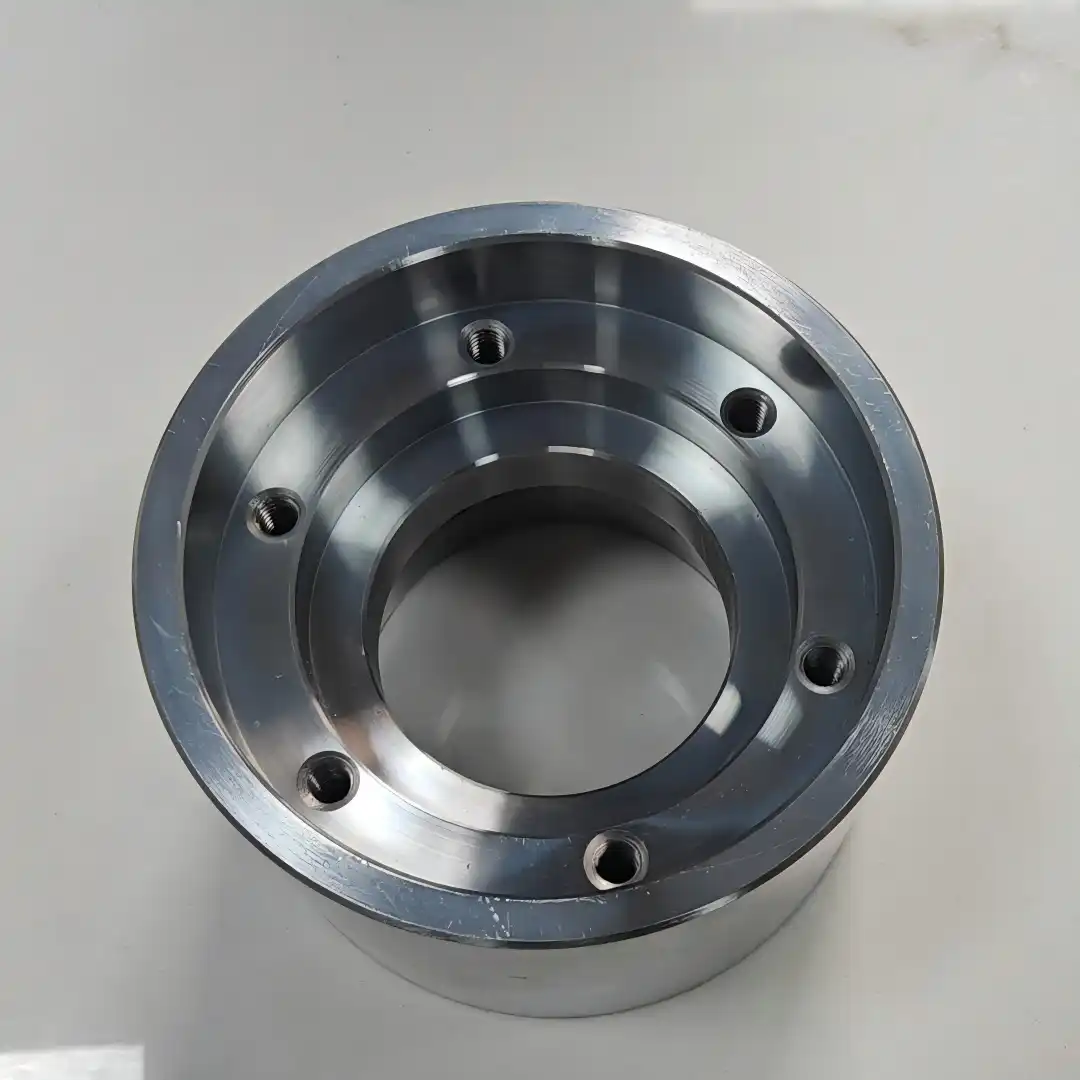
Why the prototype should use the production material
Because the test measures the material, not just geometry.
Substituting a free-machining grade for a tough one changes the machined surface, the residual stresses and the way the part yields under load. The geometry may be correct while the result is misleading, which is the most expensive outcome a prototype can produce: it validates a design that will behave differently in production.
Where the production process is not machining at all, the calculation changes. A machined prototype that will be molded later is most useful when it reproduces the mold material and the finish the mold will produce, so the assembly and the cosmetic result carry over even though the process does not.
Holding position across several critical faces
Position between features is where multi-setup machining is most likely to disappoint. Every re-clamping introduces a locating error that appears as a shift between opposite faces, and a drawing that ties several angled features to one datum is far easier to satisfy from a single setup. Where a fixture is needed instead, the design should include clamping faces that will not interfere with the measured surfaces.
The alternative is to design the part so the critical relationships live on the faces a 3-axis machine can reach. That change sometimes costs a few grams of weight and removes a fixture, which is a favourable trade on a prototype where the schedule matters as much as the mass. Drawing conventions for stating the datum relationships follow ASME standards, and inspection planning guidance is published by the NIST Manufacturing Extension Partnership.
Edge treatment on loaded parts
A sharp internal corner is a stress raiser, and on a performance part that is a design decision rather than a cosmetic one. Specifying a radius or a chamfer at the transition between a stressed face and a relieved one is often cheaper than leaving it sharp, because the cutter naturally produces a radius and hand deburring introduces variation. The same applies to the finish: a scratched or torn surface on a stressed face shortens fatigue life regardless of whether the dimensions are right.
These callouts belong on specific edges rather than everywhere. A general note that all edges must be free of burrs, plus individual radii on the transitions that carry load, communicates intent without turning the whole part into a finishing job. Surface-condition terminology follows ASTM Committee B08, and material property data for the selected grade is published by ASM International.
Verifying a performance prototype
Verification is broader than dimensional inspection for this class of part. The useful record includes the material certificate with the condition, the inspection results for the features on the drawing, and enough process information to reproduce the part later: the setup scheme, the heat-treatment sequence where applicable, and the finishing steps in order.
That record is what allows a later batch to be compared with the tested one. Without it, a change in supplier or stock lot becomes an uncontrolled variable, and a performance result can move without anyone changing the design. Process control guidance for small manufacturers is published by the NIST Manufacturing Extension Partnership, and heat-treatment terminology follows ASME and ASM International reference material. Coatings and passivation used on exposed surfaces are described in ASTM B08, and process waste handling under US EPA rules.
How to brief a performance part order
A brief for a loaded part is shorter than a full specification but more pointed. Name the grade and condition, state the features that carry load and the interfaces that must match the mating component, list the test the part has to survive, and say whether cosmetic appearance matters at all. That last point is not trivial: a part that will be photographed needs a different finishing treatment from one that will be cycled to failure in a rig.
Two further details save time later. State whether the prototype is expected to be repeatable, because that decides how much process documentation is generated alongside it, and identify any feature that will be adjusted after testing. Knowing which number is likely to move lets the supplier plan a rework path rather than treating each revision as a new part. Design guidance for the machined features involved is collected under CNC milling and standards and tolerances.
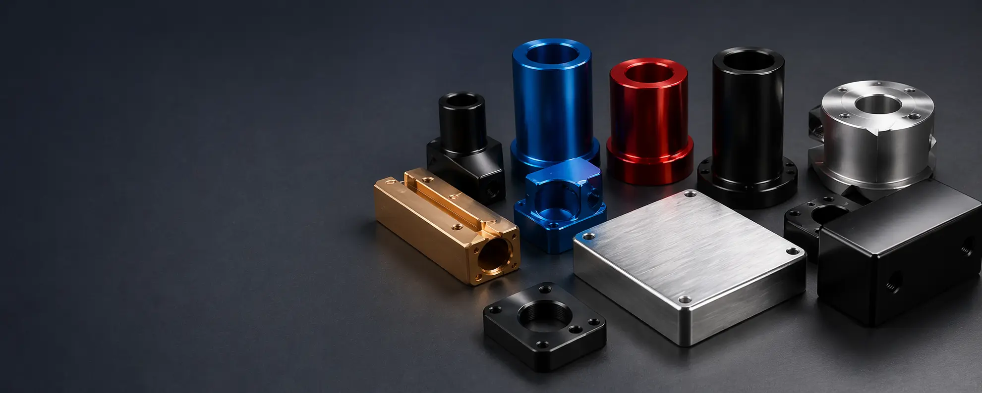
Send the model, the production material and the features that carry load, then request a quote for a performance prototype review.
FAQ
Does a performance prototype have to be made on the production process?
Not necessarily, but it must use the production material and reproduce the features that carry load. Machining a prototype for a part that will later be molded is common, provided the material and the critical interfaces match what testing needs to prove.
How many critical dimensions should a performance prototype carry?
Only the ones connected to the load path, the interfaces and the assembly. Increasing the number of controlled dimensions raises inspection time without improving performance, and it makes a genuine out-of-tolerance result harder to spot.
Can a machined surface reduce fatigue life on a loaded part?
Yes. Tool marks, torn material and sharp transitions act as stress raisers, so the finish and edge radii on stressed faces matter as much as the dimensional result, which is why they belong in the drawing callouts for those faces.