

A machined aluminium part measures perfectly, goes for anodizing, and comes back unable to accept its mating component. Nothing went wrong: the coating grew into and out of the surface, and the drawing did not account for it. Coating growth is one of the few finishing effects that is entirely predictable, which makes it one of the most avoidable sources of rework. This guide explains how the layer grows, which features it affects, how to specify an allowance or masking, and how to check coated dimensions without arguing about them afterwards.
Does anodizing add thickness to a part?
Yes, and it also penetrates the surface.
The oxide layer grows partly outward and partly into the aluminium, so external surfaces grow, bores and threads close up, and the change follows the coating class specified.
The mechanism is worth understanding because it explains the direction of every dimensional change. Anodizing converts aluminium at the surface into aluminium oxide rather than depositing a layer on top. The conversion consumes some of the original metal and produces a layer that occupies more volume than the metal it replaced, so the resulting surface sits above the original and the coating also extends below it.
The practical consequence is that all external dimensions grow and all internal features shrink, in proportion to the coating thickness. A shaft becomes larger by the outward growth of the coating, and a bore becomes smaller by the same amount on each wall. Where a part has coating on both an outer surface and the bore it fits into, the effective clearance closes twice as fast as either effect alone.
Because the change follows the class, the class belongs on the drawing. A part anodized to a harder, thicker class moves more than the same part processed to a thin cosmetic class, and the dimensional plan has to reflect which one is being applied. The tolerance framework that governs those callouts is set out on 6CProto’s standards and tolerances page.
How do the coating classes differ in growth?
Thicker classes grow more, and by a visible margin.
The governing specification sets a thickness range for each class, and because the coating grows in both directions, the dimensional effect is roughly proportional to that range.
Type II anodizing produces a relatively thin coating used for appearance and corrosion protection, and its dimensional effect on most features is small but real. Type III, the hard anodizing process, produces a considerably thicker layer intended for wear resistance, and the dimensional change is correspondingly larger. On a precision part, that difference is often the deciding factor between the two classes.
The class also determines how much the coating can be machined back afterwards. A thicker coating leaves more room to bring a feature to tolerance by removing material locally, while a thin cosmetic coating leaves very little. Where a feature must be exact after coating, that is worth considering before the class is chosen rather than after.
Specifying a class rather than a thickness is the practical route, because the specification defines the classes and the test methods that verify them. The coating and test framework is published by ASTM committee B08 on metallic and inorganic coatings, and the materials context for the aluminium substrate by ASM International.
Which features are affected most?
Threads, bores and mating faces.
Any feature that must accept or fit another component is affected, with threads and close-tolerance bores the most sensitive because they have the least clearance to spare.
Threads are the classic failure. A tapped hole anodized without protection has coating on its flanks, which reduces the effective diameter and changes the thread form. The fastener may start but bind, or it may not engage at all. The same applies to a threaded shaft, which grows and will not enter its nut. Both are entirely predictable and both have standard solutions.
Bores behave in the same way. A bore that accepts a bearing, a bushing or a shaft loses clearance by twice the coating thickness, since the coating grows inward from both sides. Where the bore was dimensioned to a nominal fit without an allowance, the assembly becomes tight or impossible. A hole intended for a clearance fit may become an interference fit.
Mating faces that seat against one another are subtler. Two flat surfaces bolted together with coating on both lose the clearance between them, which can affect how a joint closes or how much a gasket compresses. The change is small, but on a precision assembly it accumulates across several interfaces.
Features that are purely cosmetic or structural are unaffected in practice. A panel with a generous general tolerance does not care about a coating that is a fraction of its tolerance band, which is why the dimensional effort should be concentrated on the interfaces rather than applied across the whole drawing.
| Feature | Effect of coating | Usual solution |
|---|---|---|
| Tapped hole | Effective diameter reduced; thread form altered | Mask the thread or tap after coating |
| Clearance hole | Diameter reduced | Add an allowance on the drawing |
| Bore for a bearing or bushing | Clearance reduced on both sides | Allowance, or machine after coating |
| Shaft or spigot | Diameter increased | Machine to a reduced nominal |
| Mating faces | Stack-up closes slightly | Include coating in the tolerance stack |
| Electrical contact point | Coating is an insulator | Mask the contact area |
How should masking be planned?
Decide which features stay bare, and say so on the drawing.
Masking protects specific features from the coating, and because it is hand labour, the plan should include only the features that genuinely need protection.
The features that usually need masking are threads, electrical contact points, precision bores and any surface that will be bonded or used as a datum. Each is a decision the designer can make, and each adds labour to the finishing operation, so the list should be deliberate rather than comprehensive.
Two alternatives often reduce the masking requirement. Leaving an allowance on a bore or a shaft lets the coating grow and still land within tolerance, which removes a masking step. Tapping a hole after coating produces a clean thread without protection, though it removes the protective coating from the thread itself, which matters in a corrosive environment.
The choice between those approaches is a function of the part. A thread that must resist corrosion is better masked and coated; a thread in a dry indoor assembly can be tapped after coating. A bore with a generous clearance can take an allowance; a bore that locates a bearing probably needs masking or post-coating machining. Recording those decisions on the drawing is what allows the finishing shop to price the work accurately.
How does the tolerance stack change?
The coating adds to every surface it covers.
A tolerance stack that ignores coating will be wrong on any assembly where coated surfaces meet, because the coating contributes to both the size of the parts and the gaps between them.
The stack should include coating growth on each coated surface in the chain. Two bolted plates with coating on their mating faces sit slightly further apart than an uncoated stack, which affects the assembled height. A shaft in a bore with coating on both closes the clearance twice. A stack of coated parts compresses gradually across the assembly, which can matter on a long tolerance chain even when each individual contribution is small.
The practical approach is to identify the interfaces where the stack matters and to dimension those with the coating included. Everything else can carry a general tolerance, because a cosmetic surface does not need the same accounting as a locating feature. Where the stack is genuinely tight, the alternative is to mask one surface of the pair, which removes the coating from the chain entirely.
Designing for post-coating assembly is the next step, and it usually means choosing which side of an interface carries the coating. Coating the outside of a housing while masking the bore is a common arrangement, because the visible surface is protected and the interface stays at its nominal dimension.
How are coated dimensions inspected?
Measure the features that must fit, on the finished part.
Inspection should confirm the coating thickness against the specified class and verify the dimensions of the features where the coating affects function.
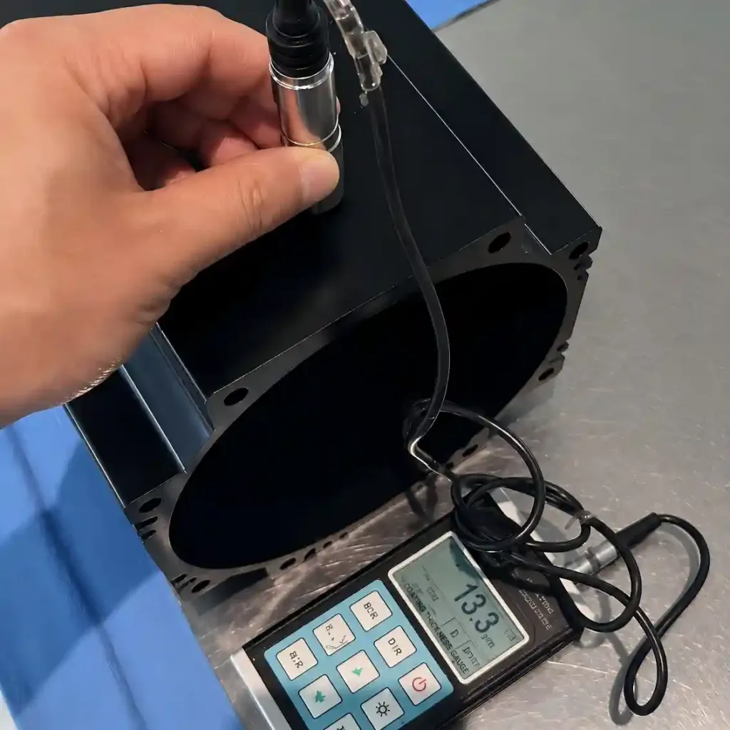
Coating thickness is measured directly with a gauge on the finished part, and the result is compared with the class on the drawing rather than with a general expectation. That measurement is the first check because it explains any dimensional variation found afterwards: a coating at the top of its class range will produce a larger dimensional change than one at the bottom.
Dimensional inspection then covers the interface features. Bores that must accept a component are checked with the gauge the assembly will use, and threaded holes are verified by running a gauge or the actual fastener. Mating faces are checked for flatness where the joint matters. Those are the features where the allowance either worked or did not.
Recording the coating thickness alongside the dimensional results makes a first article report genuinely useful, because it separates a coating variation from a machining error. Where a batch is found outside tolerance, that distinction determines whether the parts are re-machined or reprocessed.
6CProto provides quality inspection reports on request and follows each order with a dedicated project manager, so the inspection scope for a coated part can be agreed with the finishing specification. The surface preparation practice behind the coating is described in ASTM D3359, the materials engineering context by ASM International, and process waste from the finishing line is handled under the framework published by the US Environmental Protection Agency.
Specifying coating growth before machining
The dimensional effect of anodizing is predictable, which makes it a design decision rather than a finishing surprise. State the class, identify the interface features, decide for each whether it takes an allowance or masking, and include the coating in the tolerance stack where the assembly depends on it. Those four steps remove almost every failure associated with coated fits.
Two habits make them practical. Concentrate the dimensional effort on the features that mate, since a general tolerance elsewhere costs nothing. And record coating thickness with the dimensional results, so a later batch can be compared against the same conditions rather than against the nominal drawing alone. The routes available alongside anodizing are described in the surface finish guides, and post-coating design practice is covered in the 6CProto article on designing parts for plating and anodizing.
FAQ
How much thickness does anodizing add?
It depends on the class specified, which the governing specification defines as a range, and on the fact that the coating grows both outward and into the surface. Rather than working from a general number, state the class and the feature requirement: a bore that must accept a component should be dimensioned with the coating included, and the finisher’s measured thickness confirms what actually occurred on the part.
How thick is Type III anodizing compared with Type II?
Type III, the hard anodizing process, produces a considerably thicker coating than Type II, which is why it resists wear better and moves the dimensions more. Both are defined by class within the governing specification rather than by a single figure. Where a part has tight dimensional requirements, the thicker class should be chosen only when its wear properties are needed, and the allowance adjusted accordingly.
Should threads be masked or tapped after anodizing?
It depends on the environment. Masking keeps the thread coated, which protects it from corrosion, and is the usual choice for parts that will see moisture or outdoor exposure. Tapping after coating produces a clean thread with predictable engagement but leaves bare aluminium on the flanks. Where corrosion resistance matters, masking is the better answer; where it does not, tapping after coating removes a masking step from the finishing operation.
Can anodizing be removed from a feature after coating?
Yes, by machining, which is how precision bores and threads are brought back to nominal on parts that were coated all over. The machined area is bare aluminium and will not have the corrosion protection the coating provides, so it should be treated or accepted as a bare surface. Where that matters, the design should specify masking instead, so the feature is never coated in the first place. The test methods referenced in this article are published by ASTM committee D20.
If a coated part has to assemble without rework, send the model with the coating class and the features that must keep their clearance. 6CProto reviews the part alongside the finishing route, plans the allowance or masking, and returns a DFM report with the quote. Upload the file at the 6CProto quote page or send it to projects@6cproto.com.