

A powder-coated part that will not assemble is a familiar problem, and it is always the same two causes: the film closed a clearance that was dimensioned without it, or a thread was coated when it should have been protected. Unlike anodizing, powder coating builds a film on top of the surface rather than growing from it, so every coated face moves outward by roughly the film thickness and every coated bore closes by twice that. This guide covers thickness, masking, the design decisions that remove the problem, and how to check a coated part before it is packed.
How thick is powder coating?
Thicker than most designers assume for a coating.
A powder film is typically measured in thousandths of an inch or in micrometres, and it sits on the surface rather than penetrating it, so the dimensional effect is direct.
The film thickness depends on the powder type and the specification, and most industrial coating is applied within a range rather than a single value. That range exists because application is statistical: an electrostatic spray builds material unevenly across a part, so a supplier holds a band rather than a number. The band is normally quoted in the specification and verified with a gauge on the finished part.
The distinction from anodizing matters for design. Anodizing converts the surface, so roughly half of the layer grows inward and the dimensional change is smaller than the nominal thickness. Powder coating adds a film above the surface, so the outward movement is the full film thickness and an internal feature closes by twice it. A bore specified without allowance will not accept its component; a shaft intended for a slip fit will be tight.
Where the geometry is designed for it, the film is not a problem. Where it is not, the fix is either an allowance on the drawing or masking, and both decisions belong in the request rather than in a note after the parts are coated.
How does film thickness vary by powder type?
By formulation, and by the purpose the coating serves.
Different chemistries and finishes build films in different ranges, and a functional coating intended for corrosion protection is generally specified thicker than a decorative one.
The powder’s formulation sets the practical range. Fine-texture and smooth decorative powders are applied in relatively thin films to preserve their appearance, while functional powders and those intended for aggressive environments are applied thicker, since corrosion protection and abrasion resistance both scale with film build. A structured or wrinkle-finish powder is often applied at a heavier build because the texture itself requires it.
Geometry then modulates what actually happens. Sharp edges attract more powder and build a heavier film, and recessed areas can receive less. That means the thickness measured at one point on a part is not necessarily representative of the whole, which is why the specification should state a range and why inspection samples more than one location on a large component.
The practical conclusion for a design engineer is that the film’s thickness should be stated on the drawing, not inferred. A note that says “powder coat, black” without a thickness leaves the supplier to choose, and the choice determines whether the part assembles. Test methods for film measurement and coating performance are published by ASTM committee B08 on metallic and inorganic coatings.
How does coating affect threads and bores?
It closes them, usually more than expected.
A coated thread loses its clearance on both flanks and its effective diameter drops, while a coated bore closes by twice the film thickness on the diameter.
Threads are the most common casualty of an unplanned coating. The film forms on the thread flanks, and because the film is much thicker than a plating, the flank interference is enough to prevent engagement or to gall the fastener on the way in. The fix is straightforward but has to be decided in advance: mask the thread, plug the hole, or tap after coating.
Tapping after coating produces a clean thread but removes the coating from the thread itself, leaving bare metal in a location that is often the first place corrosion begins. Masking with a plug or a cap protects the thread and allows the fastener to be coated elsewhere; the labour is modest and the result is a thread that both engages and resists corrosion.
Bores behave similarly. A bore that accepts a bushing, bearing or shaft closes by twice the film thickness, so a clearance fit can become an interference fit. Masking a bore is done with a plug or a cap, or the bore can be dimensioned undersized so that the coated result lands on nominal. Where the bore is long or has a close tolerance, post-coating machining is sometimes the only reliable route, but it leaves a bare surface that may need separate protection.
Slip fits on external surfaces are affected in the other direction: a coated shaft grows, so a fit that was dimensioned to slide will tighten. Where the shaft is also visible, the film’s appearance cannot simply be removed, and the practical answer is to dimension the machined part to account for the coating.
| Feature | Effect of the film | Practical response |
|---|---|---|
| Tapped hole | Flank interference; fastener will not engage cleanly | Mask with a plug, or tap after coating |
| Clearance hole | Diameter reduced | Allowance or masking |
| Bore for a bearing or bushing | Clearance reduced by twice the film | Mask, or machine after coating |
| Shaft or spigot | Diameter increased; slip fit tightens | Dimension undersize for the film |
| Mating faces | Stack-up closes; gasket compression changes | Account for the film in the stack |
| Electrical contact point | Film is an insulator | Mask the contact area |
How should masking plugs and caps be planned?
List the features that stay bare, and keep it short.
Masking protects a feature from the coating, and because each plug or cap is applied and removed by hand, the list should contain only what genuinely needs protection.
The features that usually need masking are threads, electrical contact points, precision bores and surfaces that will be bonded rather than bolted. Each is a decision a designer can make, and each carries labour. Silicon plugs and caps are the common solution for holes and threads; tapes and lacquers are used for irregular shapes and for surfaces that cannot take a plug.
Two alternatives reduce the masking burden. Allowing for the film on a non-critical clearance hole often removes the need to mask it at all. And where a thread is not exposed to moisture, tapping after coating leaves a clean thread without the masking step, at the cost of bare metal on the flanks.
The choice belongs on the drawing because it changes the price. A part with eight masked threads costs more to process than one with two, and a supplier quoting without that information is guessing. Where the masking plan is agreed in advance, both the price and the risk of a coated thread are reduced at the same time. The tolerance framework that covers those callouts is set out on 6CProto’s standards and tolerances page, and the coating test methods are published by ASTM committee B08.
How should a coated part be designed for assembly?
Decide which side of each interface carries the coating.
A coated part assembles reliably when one surface of each interface is left bare or dimensioned for the film, rather than leaving both coated and hoping the tolerance absorbs it.
The principle is simple: coating belongs on the outside, where it protects and where it is seen, and the interface belongs where the dimension is controlled. A housing with a coated exterior and a masked bore is the common pattern; so is a bracket with a coated body and masked mounting faces. Both remove the film from the tolerance chain where it would do the most damage.
Where a part must be coated on both sides of an interface, the film has to be included in the tolerance stack on each side. That is manageable on a generous clearance and difficult on a tight fit. On a stack of several coated parts, the accumulation becomes significant enough to affect assembly, which is why the design decision is worth making at the interface level rather than for the part as a whole.
Fastener selection belongs in the same conversation. A screw with a coated head sits slightly proud, and a countersunk fastener in a coated hole will not seat flush unless the countersink is masked or the geometry is adjusted. Those are small effects that become visible on a finished product, and they are cheapest to resolve during design.
Can a coated part be repaired or touched up?
Yes, but the repair is paint, not powder.
Touch-up after curing is done with matching liquid paint, which behaves differently from the cured film and is visible under close inspection even when the colour matches.
The practical implication is that the touch-up policy should be agreed before a batch is accepted. Where a part is functional, a repaired area is usually acceptable and the decision can be left to the supplier. Where a part is cosmetic, the acceptable extent of touch-up has to be defined, along with where it may appear. Defining it after a batch is delivered turns a small concession into a negotiation. Where a repaired or recoated part must be stripped first, the resulting chemical waste is handled under the framework published by the US Environmental Protection Agency.
Some defects can be corrected by re-coating rather than touching up. A part that is under-coated or that shows a surface defect can be stripped and recoated, which restores the film’s integrity but adds a process cycle and exposes the substrate to an additional chemical treatment. That option should be reserved for parts where the film’s performance matters, not for cosmetic marks that a small repair would hide.
Preventing the need is cheaper than either option. Handling discipline between coating and packing, individual protection for cosmetic faces, and a masking plan that keeps film off the interfaces all reduce the number of parts that need repair. Those steps are the same ones that make the batch repeatable, which is why they belong in the specification rather than in a discussion after delivery.
How is a coated part inspected?
Thickness, adhesion and the interfaces.
Inspection covers film thickness measured on the part, adhesion assessed on a sample, and verification that masked or dimensioned features still function.
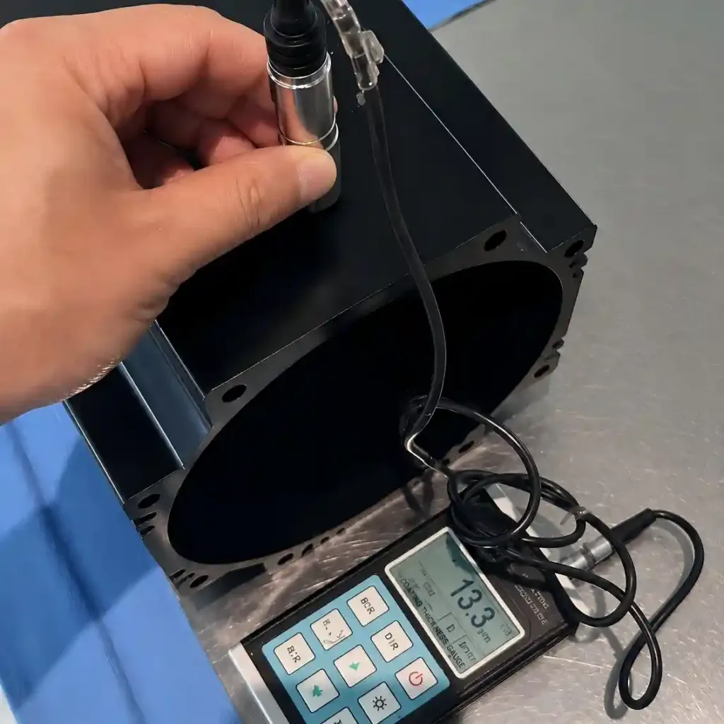
Thickness is checked with a gauge at several points on the part, since the film varies with geometry and a single reading is not representative. Adhesion is assessed by the tape method described in ASTM D3359, performed on a sample panel or a sacrificial part because the test damages the film.
Functional checks then cover the features the coating could have compromised. Threads are verified by running the intended fastener or a gauge; bores are checked with the component that will be fitted; and mating faces are checked for the fit the design expects. Those checks are quick and they catch the interference problems that dimensional inspection of the bare machined part cannot.
6CProto provides quality inspection reports on request and assigns a dedicated project manager to each order, so the inspection scope for a coated part can be agreed with the finishing specification. The quality practices behind those checks are described by NIST MEP, and process waste from the coating line is handled under the framework published by the US Environmental Protection Agency.
Designing for a coated fit
Powder coating thickness is predictable enough to design around, and the design decisions take three forms: allowance on features that can tolerate it, masking on features that cannot, and placing the coating on the side of each interface where it does no harm. Where those are made deliberately, the coating stops being a source of assembly problems.
Two habits make them practical. State the film thickness range on the drawing, so the allowance is based on a number rather than an assumption. And keep the masking list to the features that genuinely need it, since each one is labour and each one is a chance for an error. The coating routes available alongside powder coating are described in the surface finish guides, and the fabrication context for the parts themselves is covered on the sheet metal fabrication page.
FAQ
How much thickness does powder coating add?
The film sits on top of the surface, so an external face grows by roughly the film thickness and a bore closes by about twice that, since the film forms on both sides. The exact value depends on the powder and the specification, which is why the thickness range belongs on the drawing. Measuring the coated part confirms what actually occurred and lets the next batch be dimensioned against a real number.
What is a mil of coating?
A mil is one thousandth of an inch, and it is a common unit for specifying and measuring film thickness on coated parts. Powder coating specifications often state a range in mils or in micrometres, which allows the supplier to work within the band and the buyer to verify the result with a gauge. What matters for design is the range rather than the unit, because the dimensional effect follows the thickness.
Should threads be masked or tapped after powder coating?
Masking is the more protective option, because it keeps the coating off the thread flanks while leaving the fastener coated elsewhere, and it produces a thread that both engages cleanly and resists corrosion. Tapping after coating gives a clean thread but leaves bare metal on the flanks. Where the assembly sees moisture or the part is used outdoors, masking is usually the better choice despite the extra labour.
Can powder-coated parts be machined after coating?
They can, and it is sometimes the only way to bring a precision bore back to nominal. Machining removes the film locally and exposes bare substrate, which will not have the corrosion protection the coating provides, so the exposed area may need separate treatment or should be acceptable as a bare surface. Where a feature genuinely needs to stay coated and dimensionally accurate, masking or an allowance is the better planning choice. The test methods referenced in this article are published by ASTM committee D20.
If a coated part has to assemble without rework, send the model with the film thickness range and the threads or bores that must stay bare. 6CProto reviews the part together with the finishing route, plans masking and allowance, and returns a DFM report with the quote. Upload the file at the 6CProto quote page or send it to projects@6cproto.com.