

Explore Sheet Metal Processes & Supplier Selection
A weld nut can survive a reported pull test while the test bolt breaks, or appear weak because the support fixture bends the sheet in an unintended way. Without the load direction and failure record, the reported peak force may answer a different question from the one the designer intended.
Weld nut pull out testing should define a complete test arrangement. Identify which way the nut is loaded, where the sheet reacts that load and how the loading member engages the thread. Terms such as pullout and pushout are insufficient unless their physical direction is shown.
The acceptance target may be resistance to separation, resistance to rotation or retained thread function. These are different requirements and need appropriate evidence. One destructive event cannot automatically establish all three.
The fabricated assembly service provides the manufacturing context. This guide focuses on a reviewable joint test and its interpretation, without assigning a generic force threshold to a nut size. Begin with the product’s load path and the failure mode the qualification is intended to exclude.
Define pull direction and loading fixture
Draw the load path before naming the test.
Show the nut, sheet, reaction opening and loading member in section, with the force direction and thread engagement specified so the test represents the intended separation mechanism.
Loading from the nut side toward the sheet is not equivalent to pulling the nut away through a threaded member. The reaction opening also changes how much sheet can bend around the attachment. A small opening can support the joint differently from an installed panel with a broad unsupported span.
Define alignment and the means of applying load without an unintended moment. If eccentricity is part of service duty, reproduce it deliberately rather than allowing an unknown offset in a supposedly axial test.
The ASME drawing framework supports clear geometric references and dimensions for the test section. It does not set a pullout force. Include fixture dimensions in the controlled method and photograph the assembled arrangement. That lets a reviewer distinguish a qualified joint from a favorable result produced by an unusually restrictive support fixture.
Sheet thickness and weld location
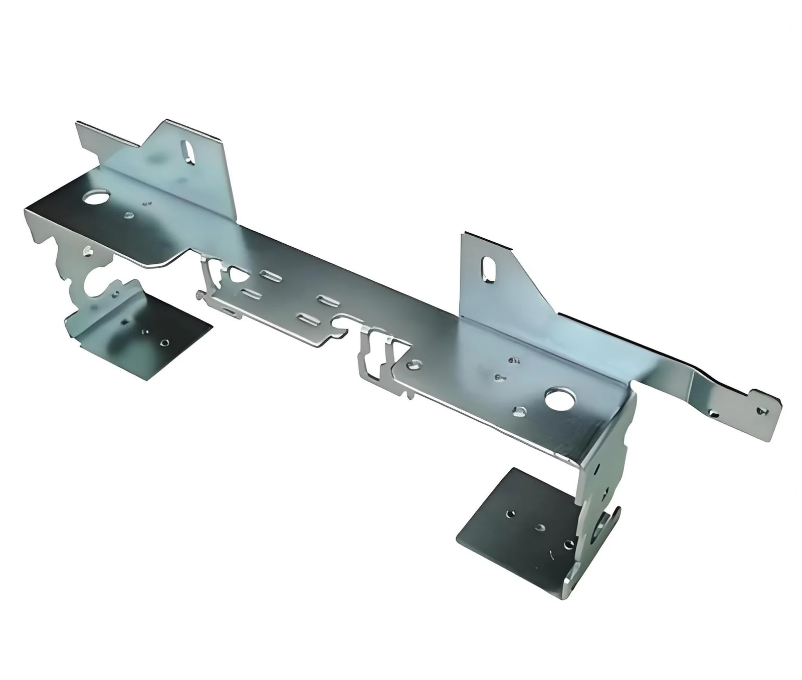
Match the specimen to the sheet condition that production will use. Material grade, thickness, coating, hole geometry and nearby bends can affect the attachment and how the sheet reacts the test load. A thicker flat coupon may remove the mechanism that governs the actual bracket.
PennEngineering’s WN product entry identifies minimum sheet thickness, hole geometry and edge distance for a specific weld-nut designation. These are product-specific installation details, not a general set of values for every welded nut.
Record the nut’s location relative to edges and formed features. A support ring placed across a nearby bend can create a test boundary absent from the installed product. Review the fixture against the actual local geometry before accepting a standard coupon format.
Keep the joining condition identifiable. Nut designation, surface condition, electrode arrangement and the applicable process revision should remain connected to the specimen. If the purpose is to establish a thickness range, challenge the relevant boundary combinations. Do not use the nominal sheet alone to imply that every permitted thickness and location has equivalent performance.
Separate pull out torque and thread failure
Axial attachment resistance and rotational resistance are different quantities. A nut can remain attached under an axial test yet rotate during tightening. Conversely, a torque test may damage the thread before it challenges the welded connection. State the intended mechanism and the units for each result.
Choose loading hardware with suitable verified capacity and engagement for the test purpose. An unsuitable bolt, damaged thread or short engagement can fail first. Such an event limits the force actually demonstrated at the joint; it does not reveal the joint’s ultimate attachment capacity.
Distinguish torque applied to the mating screw from torque causing the nut to rotate relative to the sheet. Friction and thread behavior make those different observations. A tightening torque should not be converted into a pullout force using an unexplained rule.
For sheet metal fabrication, specify the separate acceptance needs before the test is quoted. Identify whether thread inspection is required before loading, after proof loading or after a service simulation. The destructive separation specimen will not necessarily remain suitable for those other checks.
Record the failure mode and acceptance basis
Report what failed first and where. Useful categories include weld separation, sheet tearing, local bending, thread stripping, loading-bolt fracture and fixture slip. Photographs should preserve the fractured interfaces and specimen identity rather than showing only the separated components without orientation.
If the fixture slips or a loading adapter yields, evaluate whether the intended test remains valid. A machine-generated maximum value can survive in the data file even when the physical boundary changed. Mark the affected result and its disposition explicitly.
TWI’s resistance-weld quality guidance emphasizes material and process controls and retaining destructive-test records. Apply that principle to the weld-nut route while recognizing that a projection-welded nut is a specific attachment configuration.
Define acceptance before seeing the result. The product specification may require a proof load without damage, a minimum separation resistance or another criterion. The requirement and failure mode together determine the decision. Avoid choosing a threshold after testing merely because it falls below the most convenient peak in the dataset.
Nut, support and loading details on the test drawing
The test drawing should make an independent setup possible. Show enough dimensions and component identities to reproduce the load path, including the reaction opening and any spacers. Distinguish fixture geometry from the dimensions of the delivered assembly.
Use a table to connect the controlling condition with the record that demonstrates it. Establish the actual values from the approved method and product requirement.
| Condition | Controlled detail | Recorded evidence |
|---|---|---|
| Axial load | Direction and alignment | Setup section and test trace |
| Sheet reaction | Opening and support position | Fixture identity and dimensions |
| Thread loading | Bolt designation and engagement | Hardware and engagement check |
| Failure | Defined observation categories | Labeled photographs and disposition |
Include any intended displacement measurement location. Crosshead travel can include deformation in the machine and adapters as well as the joint. If permanent movement is an acceptance criterion, specify the measurement that isolates the quantity of interest rather than assuming the machine trace provides it directly.
A representative thin-panel attachment trial
Consider a hypothetical nut welded near the return of a thin bracket. The concern is separation during a service load that pulls through a mating screw. A flat coupon supported immediately beside the nut can establish an attachment observation, but it may not reproduce bracket bending.
Decide whether the test qualifies the local weld attachment or the complete bracket response. For the former, define a controlled coupon boundary. For the latter, preserve the relevant return, support span and load introduction. Give the two tests distinct names if both are needed.
Before destructive loading, confirm the specimen and fixture identities and inspect the thread and loading hardware. Record any pre-existing distortion. Afterward, retain the broken parts and identify which interface initiated the event.
NIST’s measurement-process variability discussion provides context for separating specimen differences from the test process. Repeated setup can introduce variation through alignment or contact. Investigate that variation before treating a wide force spread as proof of inconsistent welding, especially when failure locations also change between specimens.
Force, movement and thread acceptance
Connect each result to its acceptance quantity. A proof-load test asks whether the required load was sustained under stated conditions; a destructive test can investigate a limiting mechanism. Do not report the two as equivalent simply because they use the same testing machine.
Where movement matters, define its reference, load stage and residual condition. A bracket can deflect elastically during loading and recover, while a damaged attachment can retain permanent displacement. The product requirement determines which observation matters.
Evaluate thread function using the specified method and specimen condition. A loading bolt that can be removed afterward is useful observation, but it does not replace an agreed thread acceptance check. Likewise, a post-fracture thread result may be irrelevant to the pre-failure joint duty.
NIST’s uncertainty-analysis guidance explains why result quality matters to the decision. Consider the force chain, alignment and relevant dimensional checks. A calibrated load cell is part of the evidence; it does not automatically validate a fixture that changes the intended failure mechanism or a displacement reading dominated by adapter compliance.
Test scope and evidence for the weld-nut quotation
Send the assembly drawing, nut designation and test section with the quotation request. Identify the sheet grade, thickness range, coating and weld location. State whether the supplier is developing a joining route or manufacturing to an already approved specification.
Describe the requested deliverables separately: installation evidence, axial test, rotational test, thread check and final geometry. If testing consumes specimens, define their quantity and purpose through the agreed qualification plan rather than assuming destructive testing is included in ordinary piece inspection.
Request the failure record and relevant raw trace alongside the reported result. An unexplained pass statement is difficult to review when a later assembly problem suggests another mechanism. Keep deviations and retests connected to the original specimen sequence.
The standards and tolerances reference can support document discussion. The actual test method and product requirements must control acceptance. Identify who approves fixture changes, alternate loading hardware and the disposition of a test that fails outside the intended joint. Those decisions preserve the meaning of the result across repeat orders.
FAQ
Does a broken test bolt mean the weld nut passed?
It shows only that the joint sustained the load reached before the bolt event, provided the setup remained valid. Whether that establishes acceptance depends on the specified test and threshold. It does not reveal the ultimate attachment capacity. Record the bolt failure, actual force and test limitation. If the required joint behavior was not demonstrated, use suitable loading hardware and repeat under the approved method rather than silently treating the event as joint separation.
Can supplier catalogue pushout data replace an assembly test?
Catalogue data can inform selection when its exact fastener, sheet and method are understood. It does not automatically represent a different panel geometry, joining route or load direction. Compare the stated conditions with the product requirement and identify the remaining evidence needed. If an assembly test is required, define its boundary and acceptance independently rather than transferring a table value without the test sheet and fixture assumptions.
Should the reaction opening be changed when a specimen bends?
Only through a deliberate method review. Bending may be the installed product mechanism or an unwanted artifact of a test intended to isolate attachment. Changing the opening changes the support boundary and may change the result substantially. Identify the purpose, revise the controlled setup if justified and label the new series separately. Do not combine results from different openings as though they measured the same joint condition.
Conclusion
A useful pullout result describes a load path, specimen condition and observed event. Define the loading direction, sheet support and thread engagement before testing, then separate attachment failure from thread, hardware or fixture failure. The peak force becomes meaningful only within that boundary.
Keep axial resistance, rotational resistance and thread function as distinct evidence questions. Use representative geometry where the assembly response matters, and preserve the approved method when comparing production samples. If a trial fails outside the intended joint, document the limitation instead of forcing the result into a convenient pass or fail category.
For a quotation and qualification review, upload the weld-nut drawing, test arrangement and acceptance requirements. Include the required failure observations so 6CProto can assess the manufacturing and evidence scope together.
{“@context”: “https://schema.org”, “@type”: “FAQPage”, “mainEntity”: [{“@type”: “Question”, “name”: “Does a broken test bolt mean the weld nut passed?”, “acceptedAnswer”: {“@type”: “Answer”, “text”: “It shows only that the joint sustained the load reached before the bolt event, provided the setup remained valid. Whether that establishes acceptance depends on the specified test and threshold. It does not reveal the ultimate attachment capacity. Record the bolt failure, actual force and test limitation. If the required joint behavior was not demonstrated, use suitable loading hardware and repeat under the approved method rather than silently treating the event as joint separation.”}}, {“@type”: “Question”, “name”: “Can supplier catalogue pushout data replace an assembly test?”, “acceptedAnswer”: {“@type”: “Answer”, “text”: “Catalogue data can inform selection when its exact fastener, sheet and method are understood. It does not automatically represent a different panel geometry, joining route or load direction. Compare the stated conditions with the product requirement and identify the remaining evidence needed. If an assembly test is required, define its boundary and acceptance independently rather than transferring a table value without the test sheet and fixture assumptions.”}}, {“@type”: “Question”, “name”: “Should the reaction opening be changed when a specimen bends?”, “acceptedAnswer”: {“@type”: “Answer”, “text”: “Only through a deliberate method review. Bending may be the installed product mechanism or an unwanted artifact of a test intended to isolate attachment. Changing the opening changes the support boundary and may change the result substantially. Identify the purpose, revise the controlled setup if justified and label the new series separately. Do not combine results from different openings as though they measured the same joint condition.”}}]}