

Fluid systems are held together by turned parts: the fittings that connect lines, the valve components that control flow, and the manifold ports that distribute it. These parts live or die by two details — the sealing surfaces and the threads — and both are machined with precision that off-the-shelf hardware rarely matches for custom systems. This guide covers the turning priorities for fluid-system components and what to specify when ordering them.
Fluid Parts Live or Die by Sealing Surfaces
A fluid fitting or manifold port is a sealing system: the thread carries the connection, the sealing surface stops the leak, and the two must work together at the system pressure. The sealing geometry — a tapered seat, an O-ring groove, or a flat face — is machined with the accuracy that makes the seal reliable.
The turning priorities are the sealing surface condition and the geometry that positions it. A seat that is off-angle or rough leaks; a groove that is the wrong depth crushes or loses the O-ring. These are the dimensions that belong on the drawing with the seal reference, and the inspection should verify them before the part enters service.
The seal type sets the geometry. An O-ring groove is machined to the ring’s cross-section with the compression allowance; a tapered seat carries the angle and finish the fitting’s cone seals on; a flat face seals with a gasket or face seal and needs flatness and finish to match. The drawing should name the seal so the groove or seat is cut for it — a part machined to the wrong seal geometry fails at assembly, not at inspection. The sealing surface is measured, not assumed: groove dimensions are checked against the O-ring’s published envelope, the seat angle is verified, and face flatness is measured.
Thread Forms for Fittings and Ports
Threads carry the connection, and the thread form matters as much as the size. Fittings use pipe threads (tapered or parallel), metric threads, or custom forms depending on the standard and the application. The machining must match the form, the class, and the surface condition, because a thread that is cut rather than rolled behaves differently under pressure.
The specification is precise: the thread standard, the class of fit, and the sealing method. A pipe thread seals on the thread flanks; a straight thread seals on a separate face or O-ring. Mixing the two is a classic leak source. The drawing should name the standard and the seal method so the turning and inspection follow the same intent.
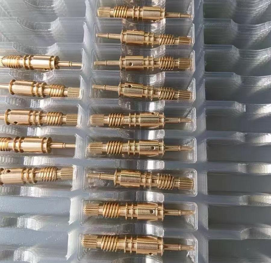
The thread standards are a family of choices: NPT and BSPT are tapered pipe threads that seal on the flanks; UNF and metric straight threads seal on a face or a separate seal; ORB and SAE fittings add O-ring sealing to straight threads. The standard is chosen for the system and the market, and the machining must match the form, the class, and the surface. Thread finish affects sealing and assembly too — a pipe thread that is too rough leaks and binds; one that is too smooth may not grip the sealant; a thread with burrs damages the mating part.
Valve Spools and Precision Fits
valve spools control flow by sliding inside a bore, and their fit defines the valve’s performance: too tight binds, too loose leaks. The turning challenge is cylindrical accuracy — the spool diameter, the roundness, and the surface finish across the length — matched to the bore it runs in.
The specification is a fit, not a single dimension: the spool and bore are designed as a pair, with clearance, roundness, and finish defined together. For prototype valves, matching the pair in one machining program removes the tolerance stacking that comes from separate sources. Roundness and straightness across the spool length matter as much as the average diameter — a spool that is oval or bowed will bind or leak even when the nominal diameter is right.
Materials for Pressure and Corrosion
Material choice follows pressure, fluid, and environment. Brass and copper suit many low-pressure and water applications and machine easily. Stainless steels handle higher pressure and aggressive fluids. Aluminum serves weight-sensitive systems where the fluid is compatible. The right material is a system decision: cost, corrosion resistance, pressure rating, and machinability all enter, and the trade-off should be explicit in the RFQ.
Surface Finish on Sealing Faces
Sealing faces need controlled surface finish — rough enough for the seal to grip, smooth enough to avoid leak paths, and consistent enough to repeat. The finish requirement is specified as an Ra value or a sealing standard, and it is verified at inspection. A sealing face is not cosmetic; the finish is functional, and it belongs on the drawing with the sealing reference.
The finish value is set by the seal. An O-ring seat needs a finish smooth enough to seal and not damage the ring; a tapered seat needs the finish the cone seals on; a gasket face needs flatness and finish for the gasket material. Specify the finish with the seal reference and the measurement method — a profilometer or comparison sample — so machining and inspection target the same number.
Documentation: Pressure and Material Test Reports
Pressure-rated fluid parts carry documentation expectations: material certificates confirm the grade, and pressure or leak test records confirm the part holds what the system needs. Define the scope in the RFQ — certificates, test records, and the standards they reference.
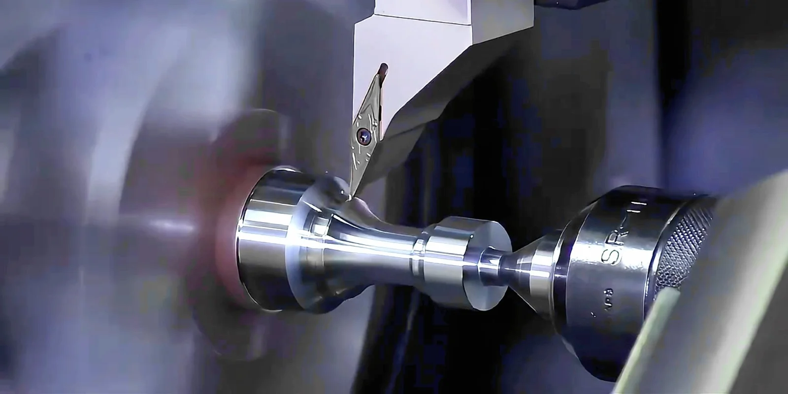
The pressure test is functional proof. A fitting or manifold that carries pressure should be tested to the rated value, with the method and acceptance specified — an air test under water, a hydrostatic test, or a helium leak test for the tightest requirements. The test defines the part’s pressure rating in practice, and the record accompanies the part. The material certificate ties the fitting to its alloy and lot, and it is the evidence behind the material selection. 6CProto’s stated documentation includes material certificates and inspection reports; for pressure-rated applications, define the test requirements and report format before quoting.
Quote Your Fluid System Parts
Fluid-system turning is sealing and threading precision in pressure-capable materials. The parts that work are specified by their function: seal method, thread standard, fit, material, and finish, with documentation to match. 6CProto’s CNC turning service produces fittings, valve components, and manifold parts in brass, stainless, and aluminum. When you request a quote, state the pressure, the fluid, the thread standards, and the sealing method, and the engineering team can confirm the turning and inspection plan.
Conclusion
Fluid-system parts are sealing and threading problems in pressure-capable materials. The quality follows the specification: seal method, thread standard, fit, material, finish, and documentation. Turning produces the accuracy these parts need, from prototype fittings to production valves. The next step is to document the pressure, fluid, thread standards, and sealing method, then request a quote that includes the finish and test requirements.
FAQs
What matters most in a machined fluid fitting? The sealing surfaces and the threads. The seal method (tapered seat, O-ring, flat face) and the thread standard define the geometry, the finish, and the inspection.
Which material should a fluid fitting use? It depends on pressure, fluid, and environment. Brass and copper suit many low-pressure and water applications; stainless handles higher pressure and aggressive fluids; aluminum serves weight-sensitive systems with compatible fluids.
How are valve spools and bores fitted? As a pair, with clearance, roundness, and finish defined together. Machining them in one program avoids the tolerance stacking that comes from separate sources.
What documentation should pressure parts include? Material certificates and, where required, pressure or leak test records. Define the scope and the standards in the RFQ so the process and price include them.