

Explore Surface Preparation, Plating & Inspection
Two suppliers can report different roughness values from the same directional surface without either instrument being broken. One trace may cross the machining grooves while another follows them. If the report omits orientation, the buyer cannot tell whether the numbers describe comparable profiles.
Surface roughness lay direction belongs in both functional specification and measurement planning. State how the predominant pattern relates to the part, the direction of motion or the interface of concern, then identify the measurement direction used to verify the requirement. These are related but distinct instructions.
A roughness amplitude does not encode that relationship by itself. Nor does a process name fully define the delivered texture when toolpath, setup and subsequent finishing can change its orientation. Inspect the actual surface in the state that the product drawing accepts.
The surface finishing service provides the manufacturing context. This guide owns direction and its interpretation, rather than a complete sealing-surface acceptance specification. The goal is a drawing and report that let engineering, manufacturing and inspection discuss the same pattern from the same references.
Read lay symbols on the drawing
Read lay relative to the identified surface reference.
Establish the governing drawing convention and view, then connect the specified pattern direction to a physical part reference rather than treating a lay symbol as an isolated roughness value.
ASME’s B46.1 surface-texture poster distinguishes lay from roughness and waviness and describes it as the predominant surface-pattern direction. That distinction is the starting point for interpreting a directional requirement, not permission to substitute one parameter for another.
Check which surface the symbol addresses and how its orientation is defined in the view. Circular, radial or crossed patterns need a relevant center or reference, while a simple directional requirement needs an identifiable line or axis. Resolve ambiguity before the machining path is selected.
Do not infer a directional limit from an amplitude callout alone. If direction matters to function but is absent from the released drawing, submit a design clarification. Record any approved sketch or supplementary note with the revision. A supplier’s familiar shop convention cannot safely replace a missing product requirement when another inspector may interpret the same surface differently.
Sliding direction and lubricant behavior
Relate the texture to the actual motion and contact. A linear slide, reciprocating contact and rotating shaft do not share one directional relationship. Identify whether movement follows, crosses or changes direction relative to the pattern over the working region.
Lay can influence how contact encounters ridges and channels, but it is not a complete friction or lubrication model. Material pair, loading, lubricant, speed and exposure remain part of the application. Avoid declaring one orientation universally superior from a surface photograph.
Separate the desired functional pattern from the easiest machining path. If the product needs a particular relationship, review whether the proposed process can produce it over the full contact zone, including curved or interrupted regions. A finishing operation may change the earlier machining lay and therefore belongs in the review.
For precision-machined interfaces, provide the motion reference with the drawing. A marked arrow and defined working area can clarify the engineering intent more effectively than an instruction to achieve a smooth surface. Validate the chosen relationship under the required operating conditions where its effect is critical to product performance.
Sealing paths across machining marks
Consider how a directional pattern relates to the relevant fluid path. The concern is not merely whether a surface looks concentric or finely machined. A connected groove or directional lead can behave differently from a texture with the same average height but another orientation.
ESP International’s radial-shaft seal guidance on finish and lead describes the effect of shaft lead in a rotating seal interface. Preserve that application context: the explanation does not establish a universal lay requirement for flat gaskets or every seal architecture.
For the drawing review, identify the seal contact region and motion direction, including reversal where applicable. A direction judged favorable in one rotation can need reassessment when motion changes. State any explicit lead or pattern requirement from the governing seal design.
Keep direction separate from complete sealing acceptance. Surface amplitude, local damage, form and the assembled operating condition require their own checks. This article’s directional review helps identify the path that needs attention; it does not turn an accepted lay observation into proof that the finished system will seal under unspecified pressure, fluid or motion conditions.
Measure across the correct direction
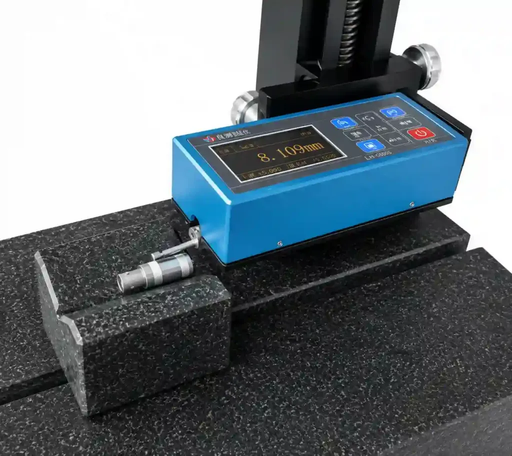
Choose the trace direction for the quantity being evaluated. A profile along a groove can capture different height variation from a profile crossing it. Record the direction relative to the physical surface and the lay, not simply the instrument’s local travel axis.
KEYENCE’s roughness-meter guidance identifies measurement direction as important and gives perpendicular-to-processing measurement as a general example. Apply the actual drawing and method requirement first; do not convert that example into an unconditional rule for every surface and parameter.
Use enough access and travel to apply the specified evaluation. On a narrow land, the preferred cross-lay direction may not provide adequate length. That is a method-planning issue to resolve before accepting an abbreviated trace as equivalent.
If an alternative method is proposed, agree what it demonstrates and how its result relates to the requirement. An areal measurement can provide directional information, but it does not automatically make a line-profile limit interchangeable with an areal parameter. Keep the reported quantity, filtering and location explicit so comparisons are meaningful across instruments and suppliers.
Direction, parameter and evaluation conditions on the report
A useful report identifies both the surface and the measurement. A value with units still leaves important ambiguity if location, orientation or filtering is missing. Connect each reported result to the zone and requirement it is intended to verify.
Use the following table to define the reporting fields before inspection. It organizes the evidence without supplying generic limits or default evaluation settings.
| Field | What to identify | Why it matters |
|---|---|---|
| Surface reference | Zone, axis and part orientation | Locates the requirement physically |
| Lay | Pattern and reference direction | Describes the accepted texture orientation |
| Trace | Path relative to lay | Defines the sampled profile |
| Evaluation | Parameter, units, length and filters | Allows a meaningful comparison |
Mitutoyo’s surface-texture measurement guide distinguishes profiles, filtering and evaluation quantities. Keep those details with the orientation record. Two readings should not be compared as a process change when their evaluation conditions differ and the effect of that difference has not been assessed.
A hypothetical cross-lay measurement comparison
Consider a hypothetical ground land with a clear linear pattern along a marked part axis. One laboratory takes its profile along that axis, while another traverses across it. Before comparing the reported values, draw both paths on the same surface view.
The cross-lay trace samples the successive ridges and valleys differently from the along-lay trace. A numerical difference can therefore arise from directional sampling rather than a change in the manufactured part. The comparison should first align method and orientation, then evaluate any remaining difference.
If the surface contains more than one predominant region, identify them separately instead of assigning a single direction from the most convenient photograph. A transition or crossed pattern can require more than one path or a different characterization method.
KEYENCE’s texture-direction parameter explanation describes an angular-spectrum-based representation of lay for area analysis. That offers one way to characterize direction, but its value remains tied to the measured area and reference axis. State those references before comparing an angular result with a drawing requirement or a profile trace from another region.
Repeat positioning and directional uncertainty
Evaluate whether the method can distinguish the directional requirement. Small changes in specimen rotation, trace location or selected region can affect the result on a strongly directional surface. Repeating a trace without moving the specimen does not assess every relevant setup contribution.
Keep the physical reference visible during inspection. A cylindrical part, for example, needs an unambiguous relationship between its axial or circumferential direction and the instrument path. Record how that relationship was established rather than describing the trace only as horizontal on the screen.
NIST’s uncertainty-analysis guidance connects measurement quality with the suitability of a result for a decision. Apply that principle to both the profile quantity and any measured direction. Instrument resolution alone cannot establish a narrowly controlled orientation on a poorly located surface.
Where the observed pattern is weak or mixed, report that limitation. Do not force a precise lay angle from an image that does not support one. Review a more suitable measurement area or method, and keep the uncertainty separate from a genuine deviation in the manufactured surface.
Drawing and inspection agreement for directional surfaces
State the functional surface, direction reference and governing convention in the released drawing package. Add the required profile or area quantity and its evaluation conditions through the appropriate specification. Keep process suggestions separate from the final surface acceptance.
Agree how inaccessible or short regions will be verified before manufacturing begins. A supplier should identify an alternative measurement proposal explicitly, with its limitations, rather than silently selecting a trace that fits the available space but measures another directional condition.
Retain the accepted report format and representative surface views. If polishing, coating or another downstream step can alter the pattern, identify the final inspection stage. Reusing an earlier report is appropriate only when it still represents the delivered requirement.
The standards and tolerances reference can support the discussion. The product documents and agreed method must establish the actual limits. Review later process and inspection changes against the direction-sensitive function, not just whether the reported amplitude remains below the same numerical threshold.
FAQ
Can an Ra result establish the lay direction?
No. Ra describes an amplitude quantity for the evaluated profile and does not by itself identify the predominant pattern orientation. A report needs the trace direction and the surface reference, with separate directional evidence where the drawing requires it. Do not infer lay from a favorable number or assume that two equal Ra values imply equivalent texture. Review the actual pattern and method alongside the amplitude requirement.
What if there is not enough width for the required cross-lay trace?
Raise the method limitation before accepting a shortened or reoriented measurement as equivalent. Review the required evaluation length, accessible region and available instrument with the acceptance owner. An alternative method may be possible, but its relation to the specified quantity must be understood and agreed. Record the proposal and limitations so a practical access problem does not become an undocumented change to the surface requirement.
Does polishing always remove directional behavior?
No such assumption is justified from the process name alone. Polishing can alter the existing pattern or introduce another one depending on how it is performed. Inspect the delivered surface after the relevant finishing sequence. If direction matters to function, keep it in the final acceptance plan and verify the actual working region. A smoother appearance or lower local roughness result does not automatically establish that the surface has become direction independent.
Conclusion
Specify lay from the part’s function and verify it from a defined physical reference. Keep pattern orientation, trace direction and amplitude evaluation distinct, then connect them in the drawing and report. That prevents a direction-sensitive surface from being accepted through an unexplained roughness number.
Use consistent locations and evaluation conditions when comparing suppliers or process trials. Where geometry prevents the intended trace, agree an alternative before release and state what it demonstrates. For sealing and sliding interfaces, directional evidence supports the application assessment without replacing the other functional requirements.
For a surface review, upload the part CAD, directional surface callouts and inspection requirements. Include the motion or interface reference so 6CProto’s DFM review can assess manufacturing and measurement access against the same functional intent.
{“@context”: “https://schema.org”, “@type”: “FAQPage”, “mainEntity”: [{“@type”: “Question”, “name”: “Can an Ra result establish the lay direction?”, “acceptedAnswer”: {“@type”: “Answer”, “text”: “No. Ra describes an amplitude quantity for the evaluated profile and does not by itself identify the predominant pattern orientation. A report needs the trace direction and the surface reference, with separate directional evidence where the drawing requires it. Do not infer lay from a favorable number or assume that two equal Ra values imply equivalent texture. Review the actual pattern and method alongside the amplitude requirement.”}}, {“@type”: “Question”, “name”: “What if there is not enough width for the required cross-lay trace?”, “acceptedAnswer”: {“@type”: “Answer”, “text”: “Raise the method limitation before accepting a shortened or reoriented measurement as equivalent. Review the required evaluation length, accessible region and available instrument with the acceptance owner. An alternative method may be possible, but its relation to the specified quantity must be understood and agreed. Record the proposal and limitations so a practical access problem does not become an undocumented change to the surface requirement.”}}, {“@type”: “Question”, “name”: “Does polishing always remove directional behavior?”, “acceptedAnswer”: {“@type”: “Answer”, “text”: “No such assumption is justified from the process name alone. Polishing can alter the existing pattern or introduce another one depending on how it is performed. Inspect the delivered surface after the relevant finishing sequence. If direction matters to function, keep it in the final acceptance plan and verify the actual working region. A smoother appearance or lower local roughness result does not automatically establish that the surface has become direction independent.”}}]}